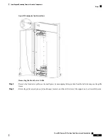


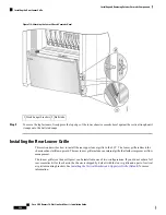


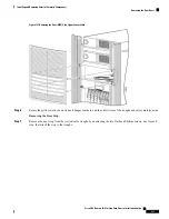
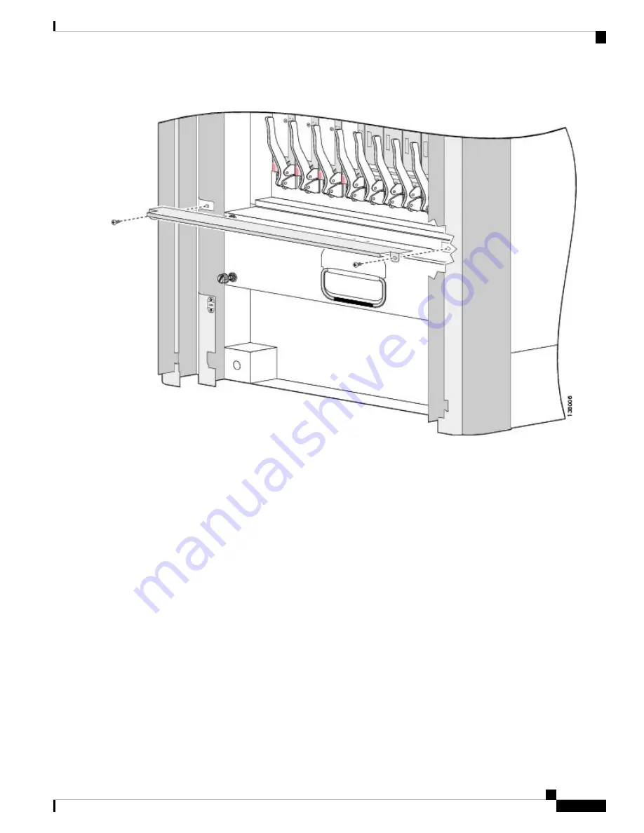
Figure 112: Attaching the Door Stop
Step 8
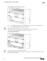
Insert and tighten the two M4 8-mm (one on each side) wafer-head Phillips screws that attach the bracket to the cable
troughs.
We recommend against using a power screwdriver to lessen the chance of stripping the screw heads.
Note
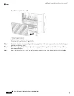
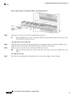
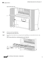
Attaching the Rear Lower Grille
Step 9
Attach the louver grille by carefully hooking the hanger brackets that are on top of the grille over the hook supports
that are on top of the vertical cable troughs (see the next figure).
Because the louver grille must be installed at the top of the chassis, it is easier and safer to stand on a ladder
while installing them.
Note
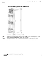
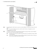
You may need to use the plastic tie wraps to attach the power shelf AC power cables to the rear of the power
shelves to provide enough clearance for the louver grille.
Note
Cisco CRS Routers 16-Slot Line Card Chassis Installation Guide
199
Installing and Removing Exterior Cosmetic Components
Steps
Содержание CRS-16-LCC/M
Страница 20: ...Cisco CRS Routers 16 Slot Line Card Chassis Installation Guide xx Preface Preface ...
Страница 118: ...Cisco CRS Routers 16 Slot Line Card Chassis Installation Guide 98 Installing and Removing Power Components Steps ...
Страница 252: ...Cisco CRS Routers 16 Slot Line Card Chassis Installation Guide 232 Upgrading Chassis Components Steps ...


