Step 15
–
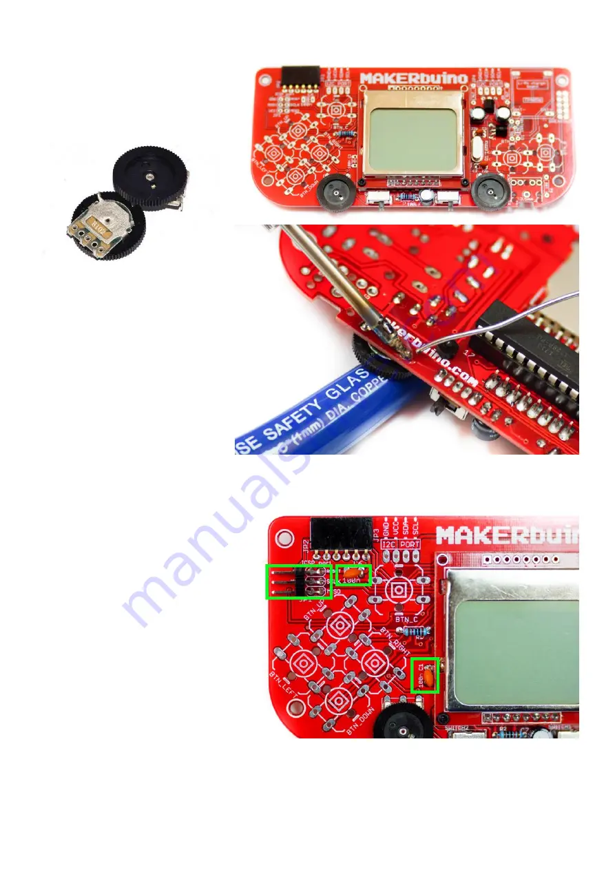
two wheel potentiometers
Now we’ll locate and solder the two trim
potentiometers labeled TR1 & TR2.
The left potentiometer is used for regulating the
screen’s backlight and
the right one regulates the
sound volume.
Make sure to use our previous pro tip here and
put your pliers underneath the potentiometers
while soldering them.
Step 16
–
3x2 ICSP header & 100nF
capacitors
The header is mounted on the top left front side
of the PCB (labeled JP1). After the header, find the
two little 100nF capacitors (they have 104 written
on their surface) and solder them on places
labeled with C1 and C6.


