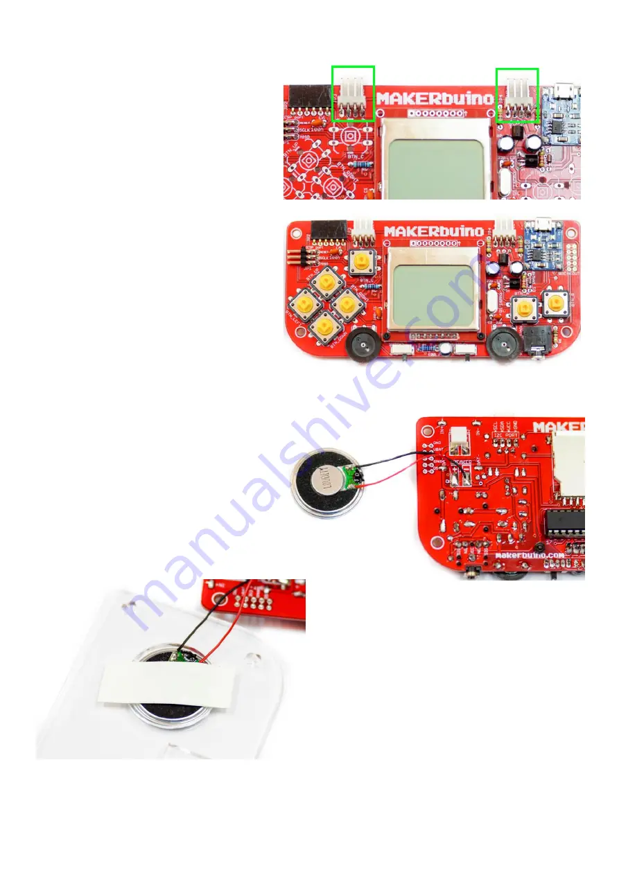
Step 20
–
male 4-pin angle multiplayer
headers
These are labeled as JP3 and JP4 on the board. Use the pro tip
about placing the pliers underneath the component because
these might be a bit harder to solder.
Step 21
–
seven big clicky pushbuttons
Finally! Time’s to solder the yellow pushbuttons.
Important: make sure to push the pushbuttons all the way
down to the PCB, otherwise they might get angled, which will
cause them to jam when you mount the front casing.
Step 22
–
connect the speaker
Let’s synthesize some bleeps and bloops!
You’ll have to connect the speaker with two tiny soft wires
that are included in the kit.
Important:
When soldering the wires to the “SPEAKER” pads
on the PCB, first apply some solder to the pads, and then
solder the wires to the pads.
Let’s fixate the speaker to the back side of the casing.
We recommend using a piece of insulating tape for this.
Alternatively, you can use a hot glue gun or some super glue.


