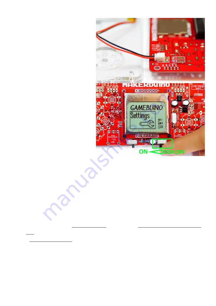
Step 12
–
first functionality test
Ok, here comes the real deal.
We’ve just soldered all of the
core MAKERbuino
components required for its basic functions and we’re going
to test them.
Connect the battery to the already soldered female battery
connector.
Turn the device on by moving the power switch into the left
position.
The screen should turn on and display some text.
If that happened, that means all of the components so far
work fine and are properly soldered feel free to proceed to
the next chapter.
Don’t worry if your screen is too dim, we’re going to fix that
in the settings when we solder the rest of the components.
It might also display the text saying “battery low, please turn
off”, don’t worry about that –
it will disappear after you
finish the settings section at the end of the build process.
If the screen
didn’t
turn on, please take a deep breath, chill, take a nap, and try the following fixes:
•
Is the microcomputer inserted into the socket on the right side? (return to step 11 and mind the notch
•
Check whether you’ve soldered the regulator and the transistor to the righ
t places (return to step 8)
•
Are the regulator and the transistor soldered to the right side? (return to step 8)
•
Check whether all of your soldering joints have a nice “volcano” shape
. Fix the joints that seem suspicious by heating them with the
soldering iron. Check the joints for bridged contacts and “unbridge” them (take a look at the first image of this chapter)
•
Are the electrolytic capacitors turned the right way (return to step 7 and mind the polarity)
•
If
you’ve
tried all of the above advice and still
can’t
figure out
what’s
wrong with your device, please send us a calm email with photos of
your
board’s
front and back side to [email protected] OR create a topic in the support category of the MAKERbuino community
forum (and include the photos of the
device’s
front and back side) OR contact us via
Facebook’s
Messenger
at www.facebook.com/makerbuino


