


Verification
7-9
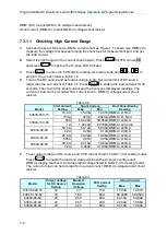
7.3.3.3 Checking Low Voltage Range
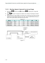
A. Connect the Load module, DC source, DMM and current shunt as Figure 7-1 shows.
Use DMM (V) to measure the voltage passing through the module’s input terminal. Be
careful in making connections so that contact resistance voltage drop will not affect the
readings.
B. Press
till VFD shows
CV
and press
to light up the L range LED indicator.
C. Press
to set load voltage and press
to set limit current. The DC Source
voltage output and limit current settings are based on the voltage/current values listed in
Table 7-13.
D. Next, press
to enable the load and wait for 30 seconds to record the voltage
passing through the negative input terminal.
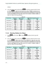
Table 7-13
Model
Load Voltage
Setting/Limit
Current
DC Source
Voltage/Limit
Current
DMM(V)
Front Panel Display
Reading
Max.
Min.
63630-600-15
75V/1A
80V/0.5A
75.1175V 74.8825V
DMM (V)±0.02675V
2V/1A
5V/0.5A
2.081V
1.919V
DMM (V)±0.0085V
63640-150-60
15V/1A
16V/0.5A
15.00775V 14.99225V DMM (V)±0.00535V
1V/1A
16V/0.5A
1.00425V 0.99575V
DMM (V)±0.00185V
63630-80-60
5V/1A
6V/0.5A
5.0085V
4.9915V
DMM (V)±0.00185V
1V/1A
6V/0.5A
1.0065V
0.9935V
DMM (V)±0.00085V
63610-80-20
5V/1A
6V/0.5A
5.0085V
4.9915V
DMM (V)±0.00185V
1V/1A
6V/0.5A
1.0065V
0.9935V
DMM (V)±0.00085V
63640-80-80
5V/1A
6V/0.5A
5.0085V
4.9915V
DMM (V)±0.00185V
1V/1A
6V/0.5A
1.0065V
0.9935V
DMM (V)±0.00085V
*If the voltage is incapable of loading as the value set, it can add load limit current or lower
down the limit current of DC Source.
7.3.4 CP Mode Verification
This test verifies if the current programming and reading value on the front panel display are
within specifications when the module is operating in CP mode. For each DMM reading, the
current displayed on the front panel should be totally the same. The voltage (DMM (V))
passes through the input or measurement terminal of module as well as the current shunt.
Shunt current = DMM (I) voltage/shunt resistance. If the voltage output of DC Source and/or
limit current setting is wrong, OPP or OCP of load module may be triggered. Press
can close the alarm screen and reset the power value.
DMM (W) load reading power = DMM (V) reading volt × DMM (I) current shunt
±
inaccuracy
DMM (V): It means the voltage measurement of DMM dc voltage.
DMM (I): It means the current shunt measurement of DMM dc voltage.
Example: Use the Table 7-14 below to analyze the example. Select model 63640-80-80 and
operate in high power range. The power accuracy is 0.3%Set + 0.3%F.S. and the panel
reading accuracy is 0.1%Set + 0.1%F.S from the specifications list, where the Vrange F.S.
should be 80V, Irange F.S. should be 80A, and the power F.S. should be Vrange F.S.
×
Irange F.S.= 80
×
80 =6400W.
MODE
RANGE
EDIT
DATA
LOAD
ENTER
Содержание 63600 Series
Страница 1: ......
Страница 2: ......
Страница 3: ...Programmable DC Electronic Load 63600 Series Operation Programming Manual Version 2 2 July 2017...
Страница 8: ...vi...
Страница 9: ...vii...
Страница 10: ...viii...
Страница 16: ......
Страница 39: ...General Information 1 19 Module outline Unit mm 142 85 62 510 36 6 32 UNIT mm 63610 80 60 63610 80 80...
Страница 40: ......
Страница 110: ...Programmable DC Electronic Load 63600 Series Operation Programming Manual 4 34...
Страница 132: ......
Страница 252: ......