


Programmable DC Electronic Load 63600 Series Operation & Programming Manual
7-10
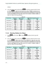
When the power is set to 400W, the power specification range is shown as follows:
DMM (W) maximum value: 400 + (0.3%
×
400 + 0.3%
×
6400) = 420.4W
DMM (W) minimum value: 400 - (0.3%
×
400 + 0.3%
×
6400) = 379.6W
Panel power reading range: DMM(W)
±
(0.1%
×
400 + 0.1%
×
6400)= DMM(W)
±
6.8W
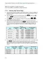
7.3.4.1 Checking High Power Range
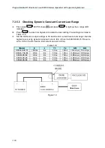
A. Connect the load module, DC Source, DMM and Current Shunt as Figure 7-1 shows.
Use DMM (W) to measure the voltage passing through the module’s input terminal. Be
careful in making connections so that contact resistance voltage drop will not affect the
readings.
B. Press
till VFD shows
CP
press
to light up the H range LED indicator.
C. Press
to set load voltage and press
to set limit current. The DC Source
voltage output and limit current settings are based on the voltage/current values listed in
Table 7-14.
D. Next, press
to enable the load and wait for 30 seconds to record the voltage
passing through the negative input terminal.
Table 7-14
Model
Load Power
Setting
DC Source
Voltage/ Limit
Current
DMM(W)
Front Panel Display
Reading (W)
Max.
Min.
63630-600-15
300W
20V/17A
327.9W
272.1W DMM (W)± 9.3W
16W
40V/0.5A
43.048W
0W DMM (W)± 9.016W
63640-150-60
400W
8V/60A
402.4W
397.6W
DMM (W)± 0.8W
10W
8V/1.25A
11.23W
8.77W DMM (W)± 0.41W
63630-80-60
300W
6V/60A
309W
271W DMM (W)± 5.1W
16W
40V/0.5A
16.48W
15.52W DMM (W)± 4.816W
63610-80-20
100W
6V/20A
105.1W
94.9W DMM (W)± 1.7W
4W
40V/0.2A
8.812W
0W DMM (W)± 1.604W
63640-80-80
400W
6V/60A
420.4W
379.6W DMM (W)± 6.8W
16W
40V/0.5A
35.248W
0W DMM (W)± 6.416W
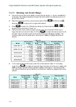
7.3.4.2 Checking Medium Power Range
A. Connect the load module, DC Source, DMM and Current Shunt as Figure 7-1 shows.
Use DMM (W) to measure the voltage passing through the module’s input terminal. Be
careful in making connections so that contact resistance voltage drop will not affect the
readings.
B. Press
till VFD shows
CP
press
to light up the M range LED indicator.
C. Press
to set load voltage and press
to set limit current. The DC Source
voltage output and limit current settings are based on the voltage/current values listed in
Table 7-15.
D. Next, press
to enable the load and wait for 30 seconds to record the voltage
passing through the negative input terminal.
MODE
RANGE
EDIT
DATA
LOAD
MODE
RANGE
EDIT
DATA
LOAD
Содержание 63600 Series
Страница 1: ......
Страница 2: ......
Страница 3: ...Programmable DC Electronic Load 63600 Series Operation Programming Manual Version 2 2 July 2017...
Страница 8: ...vi...
Страница 9: ...vii...
Страница 10: ...viii...
Страница 16: ......
Страница 39: ...General Information 1 19 Module outline Unit mm 142 85 62 510 36 6 32 UNIT mm 63610 80 60 63610 80 80...
Страница 40: ......
Страница 110: ...Programmable DC Electronic Load 63600 Series Operation Programming Manual 4 34...
Страница 132: ......
Страница 252: ......