background image

13-11-614    Page 

7

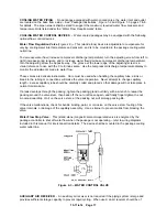
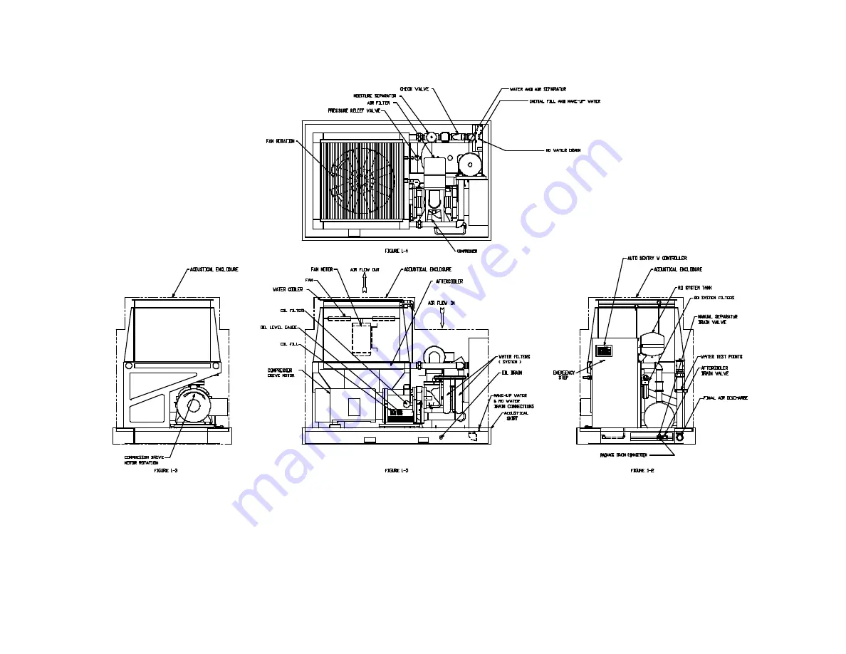
Figure 1-2 – PACKAGE ILLUSTRATION – AIR-COOLED

309EWF797-A
(Ref. Drawing)

Содержание ROTORCHAMP EWF99C-100

Страница 1: ...CHAMPION 13 11 614 Version 00 July 1 2003 ROTORCHAMP OIL FREE ROTARY SCREW COMPRESSORS MODELS EWF99C 100 125 150 HP OPERATING AND SERVICE MANUAL ...

Страница 2: ... providing fast expert maintenance and repair services For the location of your local authorized Champion Air Compressor distributor refer to the yellow pages of your phone directory or contact Factory Champion 1301 N Euclid Ave Princeton Il 61356 Phone 815 875 3321 Fax 815 872 0421 REMANUFACTURED AIRENDS Whenever an airend requires replacement or repair Champion offers an industry unique factory ...

Страница 3: ...r is used to indicate the presence of a hazard which will cause severe personal injury death or substantial property damage if the warning is ignored WARNING Warning is used to indicate the presence of a hazard which can cause severe personal injury death or substantial property damage if the warning is ignored CAUTION Caution is used to indicate the presence of a hazard which will or can cause mi...

Страница 4: ...ion 6 Section 2 Installation Coolers And Water Systems 12 Section 3 Starting Operating Procedures 21 Section 4 Controls Instrumentation 24 Section 5 Lubrication 48 Section 6 Air Filter 50 Section 7 Coupling 52 Section 8 Ro Water Filtration System 53 Section 9 Maintenance Schedule 60 Section 10 Troubleshooting 63 Section 11 Troubleshooting Auto Sentry W Controller 65 Section 12 Troubleshooting The ...

Страница 5: ... 4 1 Auto Sentry W Controller Display 26 Figure 4 2 Flow Chart For Setup Programming 29 Figure 4 3 Auxiliary Pressure Switch Receiver Unloaded Pressure Tabulation 39 Figure 4 4 Wiring Diagram Full Voltage With Expansion Board 42 Figure 4 5 Wiring Diagram Wye Delta With Expansion Board 44 Figure 4 6 Wiring Diagram Full Voltage Less Starter 46 Figure 5 1 Oil Level Gauge 49 Figure 6 1 Heavy Duty Air ...

Страница 6: ...ed and pressure increases Water is injected into the cylinder to remove the heat of compression and seal internal clearances Volume reduction and pressure increase continues until the air water mixture trapped in the interlobe cavity by the rotors passes the discharge port and is released to the air water reservoir C Each rotor cavity follows the same fill compress discharge cycle in rapid success...

Страница 7: ...13 11 614 Page 7 Figure 1 2 PACKAGE ILLUSTRATION AIR COOLED 309EWF797 A Ref Drawing ...

Страница 8: ...13 11 614 Page 8 Figure 1 3 PACKAGE ILLUSTRATION WATER COOLED 310EWF797 A Ref Drawing ...

Страница 9: ...13 11 614 Page 9 Figure 1 4 AIR COOLED SCHEMATIC 307EWF797 A Ref Drawing ...

Страница 10: ...13 11 614 Page 10 Figure 1 5 WATER COOLED SCHEMATIC 308EWF797 A Ref Drawing ...

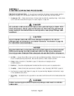
Страница 11: ...ust be performed only by qualified electricians Open main disconnect switch tag and lockout before working on the control Disconnect the compressor unit from its power source tag and lockout before working on the unit this machine is automatically controlled and may start at any time WARNING Failure to observe these notices could result in damage to equipment Stop the unit if any repairs or adjust...

Страница 12: ...harge manifold piping as lifting points DANGER The eyebolts or lugs provided on the motor are for lifting the motor only and should not be used to lift any additional weight All eyebolts must be securely tightened When lifting the motor the lifting angle must not exceed 15 degrees Failure to observe this warning may result in damage to equipment or personal injury LOCATION The compressor should be...

Страница 13: ...it with the standard enclosure requires sufficient flow Figure 2 2 page 13 for the compressor water aftercooling system and for electric motor cooling Do not block the air flow to and from the unit Allow three and one half 3 1 2 feet to the nearest obstruction on the control box end of the unit Allow three 3 feet to the nearest obstruction above and on other sides of unit For continuous efficiency...

Страница 14: ...upport for the base OIL RESERVOIR DRAIN The oil drain is piped from the bottom of the reservoir to the frame See Package Illustrations on pages 7 and 8 for details The drain connection is about 4 inches 100 mm above the floor level If this impedes oil drainage consider the following options Elevate the package of blocks to obtain the desired drain height Provide an oil sump trough below the floor ...

Страница 15: ...working at peak efficiency the incoming water supply must meet a number of requirements Please refer to the RO Water Filter Section 8 of this manual for details WARNING Back flow Preventers must be installed on the potable water supply line to the compressor to prevent high pressure air from blowing into the water supply WARNING Use of compressor initial fill and make up water not meeting all wate...

Страница 16: ...equate cooler core performance Water Cooler Pressure 100 HP 125 HP 150 HP Water flow for 30 F rise gpm All 17 8 22 0 26 3 Water Flow for 15 F rise gpm All 35 7 44 0 52 7 Maximum water flow and pressure loss gpm psi All 55 12 6 Operating pressure range psi All 40 to 150 Operating temperature range F All 60 to 90 Aftercooler Water flow for 30 F rise gpm All 1 1 1 9 2 3 Water Flow for 15 F rise gpm A...

Страница 17: ...are delicate instruments Care must be used when handling the capillary tube a kink or break in the tubing or connections will make the valve inoperative Never attempt to change capillary length excess capillary tube should be carefully coiled and placed so that damage will not take place in normal maintenance If a leak develops through the packing tighten the packing gland nut firmly with a wrench...

Страница 18: ...RVICE LINE The discharge service line connection on the unit is at base level See Package Illustrations Figure 1 2 and Figure 1 3 pages 7 8 When manifolding two or more rotary screw units on the same line each unit is isolated by the check valve in the unit discharge line If a rotary screw unit is manifolded to another compressor be sure the other compressor has a check valve in the line between t...

Страница 19: ...rature differential depends on the temperature of the air at the water injection cooler fan and the cleanliness of the core faces As ambient temperatures and core restrictions increase the injection water outlet temperature will increase The injection water outlet temperature is approximately the same as the package exhaust air temperature The outlet temperature may be checked by installing a tee ...

Страница 20: ...nd run for about 20 minutes to expel the excess grease 6 Stop the unit Replace the relief plug 7 Restart the unit WARNING Rotating machinery can cause injury or death Open main disconnect tag and lockout power supply to the starter before working on the electric motor ELECTRIC MOTOR GREASE RECOMMENDATION 30 C TO 50 C Manufacturer Trade Name Chevron SRI 2 Shell Dolium R Exxon Unirex 2 Exxon Polyrex...

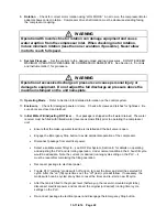
Страница 21: ...ations NOTICE Regular maintenance and replacement at required intervals of the air and water filters are necessary to achieve maximum service of this screw compressor Use only genuine Champion filters designed and specified for this compressor 2 Air Filter Inspect the air filter to be sure it is clean and tightly assembled Refer to Section 6 page 50 for complete servicing instructions Be sure the ...

Страница 22: ...al Water Fill Adjusting RO Timer Your package is shipped with all water drained The water receiver must be filled with filtered water reverse osmosis filter prior to operating the compressor unit Ensure that the make up water feed line is installed and the ball valve is open Engage the Emergency Stop button to avoid accidental operation of the compressor Disconnect package from electrical power Se...

Страница 23: ...y The unit will reach normal operating temperature in approximately 5 minutes Check the package operating information by pressing the INFO key or keypad cursor keys at any time during unit operation DAILY CHECK Refer to Section 9 Maintenance Schedule page 60 STOPPING THE UNIT Press STOP RESET key The air water reservoir will automatically blow down as the motor stops ...

Страница 24: ...to interrupt and restart the unit based on controls by others When stopped by these controls the display indicates remote stop WARNING Automatic restarting or electrical shock can cause injury or death Open tag and lockout main disconnect and any other circuits before servicing the unit In any mode the compressor will start only if reservoir pressure is below 5 psig 0 3 bars The display will indic...

Страница 25: ...t valves for flow modulation See Subtractive Valve page 39 under Other Control Devices for details Sequence Mode Operation This mode provides for communication between controllers operating only as many as are required for economical operation This is best used on applications with large storage capacity and diverse loads The lead unit will operate identically to the automatic mode operation will ...

Страница 26: ...R DISPLAY SERVICE ADVISORIES The AUTO SENTRY W controller turns on an advisory when it detects operation which needs service attention but does not warrant shutting down the compressor Some of these are normal maintenance procedures and are intended to serve as a reminder to perform routine service Others are conditions which can reduce the maximum compressor performance It will remain in effect u...

Страница 27: ... freezing The thermistor probe is also checked for open or shorted circuits and the display will indicate a fault if found CAUTION Machine damage will occur if compressor is repeatedly restarted after high temperature stops operation Find and correct the malfunction before resuming operation Water Filter Differential Pressure The pressure drop across the water filter is continually monitored by th...

Страница 28: ...losed contacts which open to shut down the package Additional external devices must be wired in series with the oil pressure switch Triggering anyone or more of the external devices will be confirmed by a single message at the controller display thus multiple triggerings must be locally identified and or reset Other messages are available e g high vibration phase relay low voltage relay and water ...

Страница 29: ...13 11 614 Page 29 Figure 4 2 FLOW CHART FOR SETUP PROGRAMMING 300EWC1255 Ref Drawing ...

Страница 30: ...n programming This enters the adjustments menu The adjustments are broken into five groups as shown in Figure 4 2 page 29 To select a group press or until the desired group is shown on the bottom line of the display Press ENTER to proceed to the group adjustments detailed below Operation Adjustments 1 In the top line DISPLAY UNITS is indicated The bottom line will indicate ENGLISH PSIG Fahrenheit ...

Страница 31: ...isplayed The bottom line will indicate a number in the range of one through eight This will be factory set at 1 This should be set to a number corresponding to the number of compressors that are currently installed on this air system that also have AUTO SENTRY W controllers It should be noted that all AUTO SENTRY W compressors on the system must have the same number programmed here to operate corr...

Страница 32: ...arge errors are detected the controller will demand that the transducer be checked 3 In the top line REMOVE RES PRESS is displayed The bottom line displays the current pressure being sensed in the reservoir The reservoir pressure transducer may now be zeroed by following the steps outlined in 2 above 4 In the top line REMOVE INJ PRESS is displayed The bottom line displays the current pressure bein...

Страница 33: ...o start up first After the countdown is complete the controller resumes the mode of operation prior to the power interruption When auto restart is enabled the green power indicator will blink whenever power is on With auto restart disabled the power indicator lights steadily while power is on SEQUENCING COMPRESSORS WITH THE AUTO SENTRY W An accessory expansion board part number 301EWC1173 is requi...

Страница 34: ...example if the number of units to be sequenced is programmed at four any compressor will start out in position four when placed in sequence mode It will then listen on the communications line for a call from the master If no call is received it will assume position three and again wait for a call from the master After another lack of a master call it assumes position two Subsequently it assumes po...

Страница 35: ...UTO SENTRY W dynamic unload point control takes over This is how it works Whenever the system pressure is below the programmed LOAD PRESSURE the PSET of each lag compressor is incremented 1 PSI every thirty seconds Thus after a short interval about five minutes in this example the PSET of the last sequenced compressor will climb up until either it equals the LOAD PRESSURE or a decrease in demand c...

Страница 36: ...NTRY W Since these pressure variations are not constant they will vary due to demand changes compressor load unload changes and number of compressors running any scheme to compensate for the pressure variations must be dynamic The exclusive dynamic unload point control feature enables this error correction scheme to be accomplished rather easily Here s how it works The master continually receives ...

Страница 37: ...ct was opened and the remote response is programmed for IMMEDIATE the compressor will immediately unload and blowdown After completion of blowdown the motors will stop and the unit will be in the REMOTE STOP mode as indicated above If the compressor was running in any mode when the contact was opened and the remote response is programmed for TIMED UNLOAD the compressor will immediately unload and ...

Страница 38: ...e system operating pressure to 75 of the relief valve set pressure and manually open the valve with the hand lever Hold the valve open for a few seconds and allow it to snap shut WARNING When the relief valve opens a stream of high velocity air is released resulting in a high noise level and possible discharge of accumulated dirt or other debris Always wear eye and ear protection and stand clear o...

Страница 39: ...turns this will prevent the valve from opening during adjustment This is also the way to deactivate the device by adjusting its pressure setting beyond the expected package operating range Operate the compressor until the desired discharge pressure is achieved in case the supply of air exceeds the demand bleed some of the discharge air to achieve the target system pressure Back out the adjustment ...

Страница 40: ... and to shut the system down if an exceedingly high water level prevails Water Solenoid Valves aa rr tt The fill tt and drain aa valves respond to the signal from the water level switches to fill or drain respectively water from the main reservoir The dump rr valve responds to signals from the PLC to dump the water charge stored in the water treatment reservoir when the compressor unit is not oper...

Страница 41: ...ion Terminal Strip This provides connections for all 110 120 volt devices not contained within the enclosure Fan and Oil Pump Starter The starter is used to provide control and overload protection for the fans and oil pump motors Overload heaters should be selected and adjusted based on the motor nameplate amps and the instructions located inside the cover of the electrical enclosure Main Starter ...

Страница 42: ...13 11 614 Page 42 Figure 4 4 WIRING DIAGRAM FULL VOLTAGE WITH EXPANSION BOARD 303EWF546 A Ref Drawing Page 1 of 2 ...

Страница 43: ...13 11 614 Page 43 303EWF546 A Ref Drawing Page 2 of 2 ...

Страница 44: ...13 11 614 Page 44 Figure 4 5 WIRING DIAGRAM WYE DELTA WITH EXPANSION BOARD 304EWF546 A Ref Drawing Page 1 of 2 ...

Страница 45: ...13 11 614 Page 45 304EWF546 A Ref Drawing Page 2 of 2 ...

Страница 46: ...13 11 614 Page 46 Figure 4 6 WIRING DIAGRAM FULL VOLTAGE LESS STARTER 305EWF546 A Ref Drawing Page 1 of 2 ...

Страница 47: ...13 11 614 Page 47 305EWF546 A Ref Drawing Page 2 of 2 ...

Страница 48: ... life can maximize the change interval Material Safety Data Sheets MSDS are available for all RotorLub lubricants from your authorized Champion distributor or by calling 815 875 3321 CAUTION Use of improper lubricants will cause damage to equipment Do not mix different types of lubricants or use inferior lubricants CAUTION Improper equipment maintenance with use of synthetic lubricants will damage...

Страница 49: ...ssor against damage by contaminated lubricant Oil Filter Maintenance Interval The oil filter element should be replaced when the oil is changed The screw on type cartridge must be set firmly against the filter head approximate 1 4 turn after making contact to avoid oil leaks Oil Breather Gear Box The breather element should be cleaned whenever the oil is changed To service unscrew the wing nut and...

Страница 50: ...n Champion compressor units Genuine parts are available through your authorized Champion distributor To service 1 Remove the wing nut and pull out the filter element 2 Visually inspect the element If cleaning is not necessary reinstall the filter element If the element requires cleaning go through Steps 3 4 and 5 3 Wash the element by soaking about 15 minutes in warm water with a mild non sudsing ...

Страница 51: ...inspection indicates a rupture crack or pin hole in the pleated media Inspection should be done by placing a bright light inside the element 2 Pressure drop across a filter with a freshly cleaned element is below three 3 inches 76 mm of water with the compressor running at full load this would indicate a rupture or crack Inlet Tube Inspect the inlet screen and tube for dirt accumulation each time ...

Страница 52: ...he collar is installed on the shaft behind one coupling body 2 Assemble the motor on the compressor 3 Working through the coupling guard opening center the coupling over the gap between the shafts maintaining the gap as shown in Figure 7 1 between the ends of the jaws on one coupling body and the flange on the opposite coupling body Tighten set screws in each coupling body 4 Insert individual cush...

Страница 53: ...rvice life It provides regular repeatable and programmable means to drain water from the close loop system thus flushing away any suspended solids It operates the filtration system independent of compressor running state Principles of Operation The system layout is shown in the Figure 1 4 page 9 and the operation of its main components will be described as follows The sediment filter hh is the 1st...

Страница 54: ...ter in the field 4 hour and 8 hour on cycles These cycles allow the field user to fill the reservoir unattended at the end of the on period the cycle freezes in time until the mode switch is toggled off on again The setting of the cycles is accomplished via wire jumpers between PLC terminals 4 5 6 7 and 9 See Figure 8 1 page 56 for details An external switch is provided to execute the program in m...

Страница 55: ...re 40 to 100 psig Working temperature 40 F to 104 F Holding tank capacity 7 0 gal 20 psig membrane air pressure 90 psig feed 6 0 gal 20 psig membrane air pressure 50 psig feed Holding tank evacuation time 3 5 minutes when filled with 90 psig feed 2 5 minutes when filled with 50 psig feed RO membrane design spiral wound TFA Sediment prefilter 5 micron element spun PPE w o end caps typical 4 psid lo...

Страница 56: ...nd no suspended solids form To conserve water longer off time cycles may be used if the resulting injection water quality does not exceed 60 ppm and no suspended solids form Adjustment of the timer for 3 days off and 3 minutes on cycles is accomplished by interconnecting PLC terminal 4 6 7 and 9 with jumper wires Refer to Fig 8 1 for PLC connections and cycle time combinations available Figure 8 1...

Страница 57: ...ifferent water parameters total chlorine free chlorine total hardness total alkalinity and pH in a single paper strip Cat No 27552 50 One other vial with 25 strips monitors total iron Cat No 27453 25 a very common contaminant rust in water pipes A test only involves inserting the test strip in a water sample and comparing the resulting color changes to a chart printed on the vial The results indic...

Страница 58: ... the valve ff feeding raw water to the RO system Open the raw and RO water test drains gg qq to depressurize the water charge from the reservoir nn and lines Unscrew the filter housing sumps by hand or with the provided spanner wrench note that the o ring may lift out of the housing and stick to the cap Remove the used cartridges and discard If signs of fouling are visible rinse out the housings a...

Страница 59: ...e must be replaced Replacing the RO membrane Turn off the valve ff feeding raw water to the RO system Open the raw and RO water test drains gg qq to depressurize the water charge from the reservoir nn and lines Disconnect the processed water line from the RO housing end cap via the quick disconnect fitting Unscrew the end cap from the housing reasonable force may have to be used Remove the used me...

Страница 60: ...her turning the petcock or removing the plug on the bottom of the filter assembly 4 Remove the nut at the top of the filter assembly while holding the filter housing to keep it from dropping When the nut is removed change the filter and reassemble 5 Repeat Steps 3 and 4 on the makeup water filter 6 Reconnect the power supply to the starter start the machine and check for leaks RO Water Filtration ...

Страница 61: ...densate in the control air filter bowl Use the manual pet cock to evacuate any accumulation and check the operation of the automatic float valve Cleanse the automatic float valve as needed 4 Check the quality of the raw incoming RO treated and injection reservoir water Refer to Section 8 for recommendations to check the water quality Every 500 Hours Operation 1 Check the delivery of filtered water...

Страница 62: ...lement Check Water Quality Check Water Flow RO Filter Discharge Check Condensate Flow at Aftercooler Separator Drain Check Condensate Level in Control Air Filter Bowl Check Setting of Buffer Air Pressure Regulator Check Setting of Buffer Water Pressure Regulator IF OIL IS ANALYZED at the end of a maintenance interval 2000 hr max and is found in good condition it may be used for the next 2000 hour ...

Страница 63: ...on 2 High discharge temperature switch malfunction 2 Replace switch 3 Blown fuse in starter control box 3 Replace fuse investigate if fuses continue to blow 4 Motor starter overload heaters trip 4 Reset and investigate cause of overload Compressor does not unload or load 1 Improperly adjusted control 1 Refer to Section 4 and adjust control 2 Air leak in control lines 2 Determine source of leak and...

Страница 64: ...low 2 Provide unrestricted supply of cooling air 3 Clogged water injection filter or cooler interior 3 Replace filter or clean cooler 4 Insufficient water cooling flow 4 Cooling water must meet minimum flow pressure and temperature requirements 5 Reservoir water level low 5 See Reservoir water level low Troubleshooting details Reservoir water level low 1 Drain valve leaking 1 Inspect and clean or ...

Страница 65: ...ped by pressing the STOP RESET key CON The compressor is operating in the Constant Run mode LDM The compressor is operating in the Low Demand mode AUTO The compressor is operating in the Automatic mode SEQ n The compressor is operating in the Sequence mode The following alternate displays may be called by pressing the or a cursor or key The key always displays DIF PRES on the first press the curso...

Страница 66: ...on the keypad by the word SHUTDOWN on the top line of the display and one of the following messages on the lower line of the display The red indicator in the Status area will be steadily lit while the conditions exist and will flash after the condition has been corrected Perform service as indicated Press the STOP RESET key to clear the shutdown Message Action Needed BAD FLOAT SWITCH 120 volts is ...

Страница 67: ... solenoid valves and all other control devices to find the cause for the inlet valve not closing Other possible causes are loose connections to the transducer electrical noise and transients or improper setting of the high pressure limit HIGH RESVR PRESS Pressure in excess of the programmed high pressure limit has been detected This shutdown will occur if a loss of pneumatic controls occurs Check ...

Страница 68: ...hat the auxiliary contact block is properly installed on the starter and wired to connector 1 terminal 4 OPEN THERMISTOR The controller has detected an open connection to the airend discharge thermistor This normally indicates a loose or broken connection at the controller connector 7 check and correct the connection This could also be indicating a broken wire or thermistor probe OPEN XDUCER Signa...

Страница 69: ...d into an operating mode e g AUTO press the STOP RESET key to put the control into the READY state then start by pressing the START key In AUTOMATIC and SEQUENCE modes compressors will not start until the pressure drops below the load pressures Display indicates NOT BLOWN DOWN The controller prevents attempts to start the main motor if the reservoir pressure is over 5 psig Pressure continues to be...

Страница 70: ...Refer to the operating instructions for further information Display is illegible The LCD contrast is adjustable from all black to all green To adjust find the small adjustment screw located on the larger circuit board behind the keypad Using a small screwdriver adjust for the most pleasing display Erratic pressures in SEQUENCE only The sequencing system transmits low level signal between units to ...

Страница 71: ...ank nn under pressurized Adjust membrane air pressure 15 20 psi Storage tank membrane ruptured Replace storage tank Isolation valve pp turned off Open isolation valve Fill valve tt leaking or stuck open Cleanse or replace Problem High TDS product water Reasons Solutions Membrane fouled Fast flush or replace TDS increased in raw water feed Check that TDS 1800 ppm Membrane fouled Fast flush or repla...

Страница 72: ...Regulator 39 Water Pressure Relief Valve 39 Water Solenoid Valves 40 Controls Instrumentation Section 4 24 Coolers Water Systems Section 2 12 Compression Injection Water System Check 19 Compressor Water Specifications 15 Cooling Water Control Devices 17 Cooling Water Piping 17 Cooling Water Specifications 15 Water Flow Requirements 16 Water Quality 16 Water System 6 Coupling Section 7 52 General I...

Страница 73: ...ency Stop 27 External Device 28 High Pressure 27 High Temperature 27 High Water Level 27 Motor Protective Devices 27 Other 28 Power Failure 28 Water Filter Differential Pressure 27 Starting Operating Procedures Section 3 21 Starting The Unit 23 Stopping The Unit 23 Troubleshooting Auto Sentry W Controller Section 11 65 Advisory Troubleshooting Guide 66 Controls Troubleshooting Guide 69 Display Mod...

Страница 74: ... initial use or 15 months from date of shipment to first purchaser whichever occurs first LABOR TRANSPORTATION AND INSPECTION The Company will provide labor by Company representative or authorized service personnel for repair or replacement of any product or part thereof which in the Company s judgment is proved not to be as warranted Labor shall be limited to the amount specified in the Company s...

Страница 75: ...North Euclid Avenue Princeton Illinois 63156 USA Phone 815 875 3321 Fax 815 872 0421 E mail champion championpneumatic com Plants in Princeton IL and Manteca CA Due to Champion s continuing product development program specification and materials are subject to change without notice ...

Отзывы: