


13-11-614 Page 22
8.
Rotation
- Check for correct motor rotation using “JOG MODE.” An arrow on the compressor/motor
adaptor shows correct rotation. Compressor drive shaft rotation must be clockwise standing facing
the compressor coupling..
WARNING
Operation with incorrect motor rotation can damage equipment and cause
water eruption from the compressor inlet. When checking motor rotation,
induce minimum rotation (less than one revolution if possible). Never allow
motor to reach full speed.
9.
System Pressure
- Set the controls to the desired unload and load pressures. DO NOT EXCEED
MAXIMUM OPERATING PRESSURE ON COMPRESSOR NAMEPLATE. See Section 4, “Controls
and Instrumentation”, for procedure.
WARNING
Operation at excessive discharge air pressure can cause personal injury or
damage to equipment. Do not adjust the full discharge air pressure above the
maximum stamped on the unit nameplate.
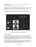
10.
Operating Mode
- Refer to Section 4 for detailed information on the control system.
11.
Enclosure
- Check for damaged panels or doors. Check all screws and latches for tightness. Be
sure doors are closed and latched.
12.
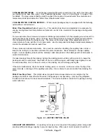
Initial Water Fill/Adjusting RO Timer
- Your package is shipped with all water drained. The water
receiver must be filled with filtered water (reverse osmosis filter) prior to operating the compressor
unit:
•
Ensure that the make-up water feed line is installed and the ball valve is open.
•
Engage the Emergency Stop button to avoid accidental operation of the compressor.
•
Disconnect package from electrical power.
•
Select a suitable water fill cycle – see RO Filter System, Section 8, for details on operating
and adjusting the PLC and its timing operation. Under normal conditions, the 8 hour-fill cycle
would be adequate. Note the current (or desired) running cycle setting on the PLC – it
must be reset after completing the filling operation.
•
Reconnect package to electrical power.
•
Toggle PLC “run/stop” mode switch off and on to reset the timer and start the selected fill
cycle. After the “on” (fill) cycle times out, the “off” (rest) cycle will follow. If necessary, the
mode switch can be cycled at any time to reset the timer and re-start a new fill cycle.
•
After the tank is filled to the proper level (half-way up the reservoir-mounted sight tube),
disconnect electrical power, and reconnect the original (or desired) running timer cycle
settings on the PLC.
•
Re-connect package to electrical power and disengage the Emergency Stop button.
Содержание ROTORCHAMP EWF99C-100
Страница 7: ...13 11 614 Page 7 Figure 1 2 PACKAGE ILLUSTRATION AIR COOLED 309EWF797 A Ref Drawing ...
Страница 8: ...13 11 614 Page 8 Figure 1 3 PACKAGE ILLUSTRATION WATER COOLED 310EWF797 A Ref Drawing ...
Страница 9: ...13 11 614 Page 9 Figure 1 4 AIR COOLED SCHEMATIC 307EWF797 A Ref Drawing ...
Страница 10: ...13 11 614 Page 10 Figure 1 5 WATER COOLED SCHEMATIC 308EWF797 A Ref Drawing ...
Страница 29: ...13 11 614 Page 29 Figure 4 2 FLOW CHART FOR SETUP PROGRAMMING 300EWC1255 Ref Drawing ...
Страница 43: ...13 11 614 Page 43 303EWF546 A Ref Drawing Page 2 of 2 ...
Страница 44: ...13 11 614 Page 44 Figure 4 5 WIRING DIAGRAM WYE DELTA WITH EXPANSION BOARD 304EWF546 A Ref Drawing Page 1 of 2 ...
Страница 45: ...13 11 614 Page 45 304EWF546 A Ref Drawing Page 2 of 2 ...
Страница 46: ...13 11 614 Page 46 Figure 4 6 WIRING DIAGRAM FULL VOLTAGE LESS STARTER 305EWF546 A Ref Drawing Page 1 of 2 ...
Страница 47: ...13 11 614 Page 47 305EWF546 A Ref Drawing Page 2 of 2 ...


