13-11-614 Page 70
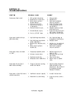
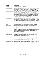
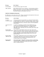
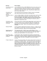
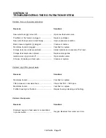
Message
Action Needed
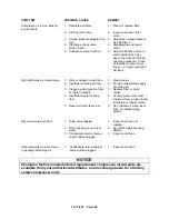
Compressor runs, but
does not load
In the CONSTANT RUN and LOW DEMAND modes, the compressor will not
load until the pressure drops below load pressure. Refer to the operating
instructions for further information. If pressure is below the load pressure,
check that the inlet valve operates freely. Check that the unloader valve is
wired and operating properly.
Compressor runs,
unloads at low
pressure
If the inlet valve closes at low pressure, check the wiring to the blowdown
valve and the piping and check valves in its discharge line.
Compressor does not
unload
The W controller operates the inlet valve to maintain pressure near the unload
pressure, matching delivery to demand. If the pressure continues to rise
above unload pressure, check that the inlet valve operates freely, and that
control air is supplied to the unloader solenoid valve. If normal unload control
does not close the valve, it will be closed during a blowdown as pressure
approaches the high pressure limit.
Compressor cycles
rapidly between load
and unload
The external air receiver should be sized appropriately to prevent rapid cycles
The rapid response time in the CONSTANT RUN mode will operate with
small receivers, but any plant air system will operate more efficiently with
adequately sized storage. Refer to the operating instructions for further
information.
Display is illegible.
The LCD contrast is adjustable from all black to all green. To adjust, find the
small adjustment screw located on the larger circuit board behind the keypad.
Using a small screwdriver, adjust for the most pleasing display.
Erratic pressures in
SEQUENCE only
The sequencing system transmits low-level signal between units to
communicate pressures. Units must be properly grounded to a good ground
system. The communications cable should use only appropriate quality
cable, and the cable should be run in its own conduit.
Compressor cycles
rapidly in SEQUENCE
mode only
In the sequence mode, the operating system requires all compressors be
piped directly to receiver, such that all transducers sense the same pressure.
Check valves or restrictions between compressors and the storage will cause
system instability. Run units in AUTOMATIC mode until the system is
corrected.
Pressure display error.
Accuracy of the pressure display and controls requires that the controller and
transducers be calibrated together. This MUST be done with no pressure at
the transducer, or errors will occur. This is easiest to check with all pressure
removed. All pressure displays should indicate 0 psi (0 bar) +1 psi. If the
display indicates greater pressures, recalibrate the system as instructed in the
configuration adjustments. Note: reservoir pressure may drop below zero
psig when the compressor is stopped, but will return slowly to zero as the
vacuum is relieved.
Содержание ROTORCHAMP EWF99C-100
Страница 7: ...13 11 614 Page 7 Figure 1 2 PACKAGE ILLUSTRATION AIR COOLED 309EWF797 A Ref Drawing ...
Страница 8: ...13 11 614 Page 8 Figure 1 3 PACKAGE ILLUSTRATION WATER COOLED 310EWF797 A Ref Drawing ...
Страница 9: ...13 11 614 Page 9 Figure 1 4 AIR COOLED SCHEMATIC 307EWF797 A Ref Drawing ...
Страница 10: ...13 11 614 Page 10 Figure 1 5 WATER COOLED SCHEMATIC 308EWF797 A Ref Drawing ...
Страница 29: ...13 11 614 Page 29 Figure 4 2 FLOW CHART FOR SETUP PROGRAMMING 300EWC1255 Ref Drawing ...
Страница 43: ...13 11 614 Page 43 303EWF546 A Ref Drawing Page 2 of 2 ...
Страница 44: ...13 11 614 Page 44 Figure 4 5 WIRING DIAGRAM WYE DELTA WITH EXPANSION BOARD 304EWF546 A Ref Drawing Page 1 of 2 ...
Страница 45: ...13 11 614 Page 45 304EWF546 A Ref Drawing Page 2 of 2 ...
Страница 46: ...13 11 614 Page 46 Figure 4 6 WIRING DIAGRAM FULL VOLTAGE LESS STARTER 305EWF546 A Ref Drawing Page 1 of 2 ...
Страница 47: ...13 11 614 Page 47 305EWF546 A Ref Drawing Page 2 of 2 ...

