


13-11-614 Page 12
SECTION 2
INSTALLATION, COOLERS AND WATER SYSTEMS
GENERAL
- On receipt of the unit, check for any damage that may have occurred during transit or
handling. Report any damage or missing parts as soon as possible.
CAUTION
Do not electric weld on the compressor or base; bearings can be damaged by
passage of current.
LIFTING UNIT
- Proper lifting and/or transporting methods must be used to prevent damage. Tow motor
fork clearance is provided by the equipment isolators bolted to the base of the unit. The unit may also be
moved into location by rolling on bars.
CAUTION
Lift compressor unit by base only. Do not use other places such as motor,
compressor or discharge manifold piping as lifting points.
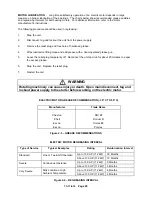
DANGER
The eyebolts or lugs provided on the motor are for lifting the motor only and
should not be used to lift any additional weight. All eyebolts must be securely
tightened. When lifting the motor, the lifting angle must not exceed 15 degrees.
Failure to observe this warning may result in damage to equipment or personal
injury.
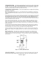
LOCATION
- The compressor should be installed in a clean, well-lighted, and ventilated area with ample
space all around the unit for maintenance. Select a location that provides a cool, clean, and dry source of
air. In some cases it may be necessary to install the air filter at some distance from the compressor to
obtain proper air supply.
WARNING
Do not install this compressor in a location that may be subject to temperatures
below 32
°
F. (0
°
C).
Below freezing temperatures will cause damage to the compressor.
Содержание ROTORCHAMP EWF99C-100
Страница 7: ...13 11 614 Page 7 Figure 1 2 PACKAGE ILLUSTRATION AIR COOLED 309EWF797 A Ref Drawing ...
Страница 8: ...13 11 614 Page 8 Figure 1 3 PACKAGE ILLUSTRATION WATER COOLED 310EWF797 A Ref Drawing ...
Страница 9: ...13 11 614 Page 9 Figure 1 4 AIR COOLED SCHEMATIC 307EWF797 A Ref Drawing ...
Страница 10: ...13 11 614 Page 10 Figure 1 5 WATER COOLED SCHEMATIC 308EWF797 A Ref Drawing ...
Страница 29: ...13 11 614 Page 29 Figure 4 2 FLOW CHART FOR SETUP PROGRAMMING 300EWC1255 Ref Drawing ...
Страница 43: ...13 11 614 Page 43 303EWF546 A Ref Drawing Page 2 of 2 ...
Страница 44: ...13 11 614 Page 44 Figure 4 5 WIRING DIAGRAM WYE DELTA WITH EXPANSION BOARD 304EWF546 A Ref Drawing Page 1 of 2 ...
Страница 45: ...13 11 614 Page 45 304EWF546 A Ref Drawing Page 2 of 2 ...
Страница 46: ...13 11 614 Page 46 Figure 4 6 WIRING DIAGRAM FULL VOLTAGE LESS STARTER 305EWF546 A Ref Drawing Page 1 of 2 ...
Страница 47: ...13 11 614 Page 47 305EWF546 A Ref Drawing Page 2 of 2 ...


