13-11-614 Page 38
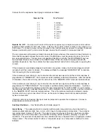
To use this relay, connect the supply wire for the remote circuit to terminal 21 (relay common) on the
terminal strip. Connect a wire to the indicator from either terminal 19 (normally open) or from terminal 20
(normally closed). Connect the other side of the indicator to its neutral.
Serial Communications
– If units are NOT connected in sequence, the RS-485 port may be used for
multi-drop communications of compressor data to external monitoring system. Data available include all
pressures and temperatures, and a report of internal service data. Version 1.10 or later software is
required in the controller. Data communications are accessible with a PC or PLC with an appropriate
communications port. For protocol information, request Drawing 301EWC1255.
OTHER CONTROL DEVICES
In addition to the electronic controller noted above, the following components are also used to control
operation of the compressor unit. Refer to air/water schematic, Figure 1-4, page 9, for their relative
location.
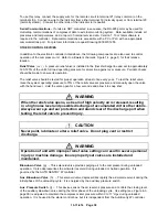
Relief Valve
(vv) - A pressure relief valve is installed in the final discharge line and set to approximately
120-125% of the unit’s full load operating pressure for protection against over pressure. Periodic checks
should be made to ensure its operation.
The relief valve should be tested for proper operation at least once every year. To test the relief valve,
raise the system operating pressure to 75% of the relief valve set pressure and manually open the valve
with the hand lever. Hold the valve open for a few seconds and allow it to snap shut.
WARNING
When the relief valve opens, a stream of high velocity air is released, resulting
in a high noise level and possible discharge of accumulated dirt or other debris.
Always wear eye and ear protection and stand clear of the discharge port when
testing the relief valve to prevent injury.
CAUTION
Never paint, lubricate or alter a relief valve. Do not plug vent or restrict
discharge.
WARNING
Operation of unit with improper relief valve setting can result in severe personal
injury or machine damage. Insure properly set valves are installed and
maintained.
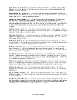
Blowdown Valve
(g) - This solenoid valve provides purging air to the compressor during unloaded
operation. It also depressurizes the air/water reservoir during unloaded or halted operation. It is
governed by the AUTO SENTRY W controller.
Aux. Blowdown Valve
(h) – This solenoid valve depressurizes rapidly the air/water reservoir during the
initial phase of the unloading cycle. It is energized by the auxiliary pressure switch.
Aux. Pressure Switch
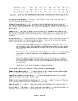
(j) – This device senses the air reservoir pressure and controls the closing level
of the auxiliary blowdown valve during the latter phase of the unloading cycle. Its setting (see Figure 4-3,
page 39) is adjusted to maintain the compressor inlet pressure within 0 to 11” Hgv during unloaded
operation. It is housed in the starter control box, but it is independent from the AutoSentry W controller.
Содержание ROTORCHAMP EWF99C-100
Страница 7: ...13 11 614 Page 7 Figure 1 2 PACKAGE ILLUSTRATION AIR COOLED 309EWF797 A Ref Drawing ...
Страница 8: ...13 11 614 Page 8 Figure 1 3 PACKAGE ILLUSTRATION WATER COOLED 310EWF797 A Ref Drawing ...
Страница 9: ...13 11 614 Page 9 Figure 1 4 AIR COOLED SCHEMATIC 307EWF797 A Ref Drawing ...
Страница 10: ...13 11 614 Page 10 Figure 1 5 WATER COOLED SCHEMATIC 308EWF797 A Ref Drawing ...
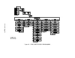
Страница 29: ...13 11 614 Page 29 Figure 4 2 FLOW CHART FOR SETUP PROGRAMMING 300EWC1255 Ref Drawing ...
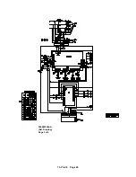
Страница 43: ...13 11 614 Page 43 303EWF546 A Ref Drawing Page 2 of 2 ...
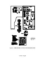
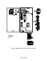
Страница 44: ...13 11 614 Page 44 Figure 4 5 WIRING DIAGRAM WYE DELTA WITH EXPANSION BOARD 304EWF546 A Ref Drawing Page 1 of 2 ...
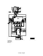
Страница 45: ...13 11 614 Page 45 304EWF546 A Ref Drawing Page 2 of 2 ...
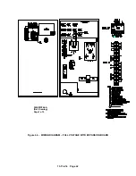
Страница 46: ...13 11 614 Page 46 Figure 4 6 WIRING DIAGRAM FULL VOLTAGE LESS STARTER 305EWF546 A Ref Drawing Page 1 of 2 ...
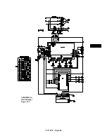
Страница 47: ...13 11 614 Page 47 305EWF546 A Ref Drawing Page 2 of 2 ...

