
13-11-614 Page 63
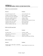
SECTION 10
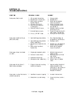
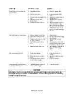
TROUBLESHOOTING
SYMPTOM
POSSIBLE CAUSE
REMEDY
Compressor fails to start
1. Wrong lead connections.
1. Change leads.
2. Blown fuses in control box.
2. Replace fuse.
3. Motor starter overload
heaters tripped.
3. Reset and investigate
cause of overload.
4. Pressure in reservoir.
4. Inspect blowdown valve.
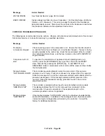
5. Read error message on
control panel.
5. Take appropriate action.
See Section 4.
6. Remote Contact is open.
6. Replace switch or jumper
(terminals 6 & 9).
7. External device is open.
7. Inspect oil pressure switch
and replace, if necessary.
8. PLC is in “STOP” mode.
8. Set switch to “RUN” mode.
Compressor starts but stops
after a short time
1. High discharge temperature.
1. See “High discharge air
temperature”, this Section.
2. High discharge temperature
switch malfunction.
2. Replace switch.
3. Blown fuse in starter/control
box.
3. Replace fuse (investigate if
fuses continue to blow).
4. Motor starter overload
heaters trip.
4. Reset and investigate
cause of overload.
Compressor does not unload
(or load)
1. Improperly adjusted control.
1. Refer to Section 4 and
adjust control.
2. Air leak in control lines.
2. Determine source of leak
and correct.
3. Restricted control line.
3. Clean control lines.
4. Blowdown valve malfunction.
4. Repair, clean or replace
valve.
Compressor shuts down or
falters while unloading
1. Purge air pressure reaching
airend is excessive.
1. Adjust auxiliary blowdown
pressure switch to the
proper level. See Section 4
for adjustment details.
Replace if defective.
Compressor cycles from load to
unload excessively
1. Insufficient receiver capacity.
1. Increase receiver size.
2. Restriction in control tubing.
2. Inspect and clean control
tubing.
Содержание ROTORCHAMP EWF99C-100
Страница 7: ...13 11 614 Page 7 Figure 1 2 PACKAGE ILLUSTRATION AIR COOLED 309EWF797 A Ref Drawing ...
Страница 8: ...13 11 614 Page 8 Figure 1 3 PACKAGE ILLUSTRATION WATER COOLED 310EWF797 A Ref Drawing ...
Страница 9: ...13 11 614 Page 9 Figure 1 4 AIR COOLED SCHEMATIC 307EWF797 A Ref Drawing ...
Страница 10: ...13 11 614 Page 10 Figure 1 5 WATER COOLED SCHEMATIC 308EWF797 A Ref Drawing ...
Страница 29: ...13 11 614 Page 29 Figure 4 2 FLOW CHART FOR SETUP PROGRAMMING 300EWC1255 Ref Drawing ...
Страница 43: ...13 11 614 Page 43 303EWF546 A Ref Drawing Page 2 of 2 ...
Страница 44: ...13 11 614 Page 44 Figure 4 5 WIRING DIAGRAM WYE DELTA WITH EXPANSION BOARD 304EWF546 A Ref Drawing Page 1 of 2 ...
Страница 45: ...13 11 614 Page 45 304EWF546 A Ref Drawing Page 2 of 2 ...
Страница 46: ...13 11 614 Page 46 Figure 4 6 WIRING DIAGRAM FULL VOLTAGE LESS STARTER 305EWF546 A Ref Drawing Page 1 of 2 ...
Страница 47: ...13 11 614 Page 47 305EWF546 A Ref Drawing Page 2 of 2 ...


