13-11-614 Page 39
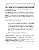
Model Power – bhp
100
100
100
125
125
125
150
150
150
Line Pressure – psig
100
125
150
100
125
150
100
125
150
Receiver Pressure – psig
20
20
27
20
20
34
38
20
27
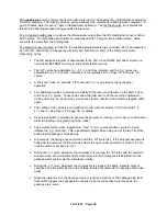
Figure 4-3 – AUXILIARY PRESSURE SWITCH/RECEIVER UNLOADED PRESSURE TABULATION
Check Valve (Aux Blowdown)
(i, next to b) – This check valve prevents back flow of air from the
airend immediately after halting operation.
Minimum Pressure Valve
(k) - This spring-loaded, pressure-balance device remains closed with
compressor discharge pressures under 65 to 70 psig, thus ensuring back pressure to promote injection
water flow for cooling and sealing. The valve also prevents back flow of system air when the compressor
is not running.
Inlet Valve
(b) – This device modulates the flow of air entering the compressor and checks the back
flow of air immediately after halting compressor operation. Its piston assembly is energized with air from
the subtractive valve (during modulation) or with air from the main blowdown valve (during unloaded
operation).
Subtractive Valve
(q) – This device produces a variable pneumatic signal (0 to 20 psig) in proportion to
a system pressure rise (0 to 10 psig) above its set pressure. It is used to control the flow modulating
action of the inlet valve. The device is adjusted as follows:
•
Loosen the locknut securing the adjusting stem of the subtractive valve and screw the latter
in several turns – this will prevent the valve from opening during adjustment. This is also the
way to deactivate the device by adjusting its pressure setting beyond the expected package
operating range.
•
Operate the compressor until the desired discharge pressure is achieved – in case the supply
of air exceeds the demand, bleed some of the discharge air to achieve the target system
pressure.
•
Back-out the adjustment stem until the subtractive valve starts to bypass air – the adjacent
pressure gauge should register movement of less than 1 psig. Now the device is ready to
feed a proportional air signal to the inlet poppet valve as the system pressure builds beyond
the present level.
•
Tighten the lockout to secure the position of the adjustment stem.
The subtractive valve can be disassembled and the diaphragm and ports cleaned.
Water Pressure Relief Valve
(ss) – This device protects the water treatment filtration system against
75 psig overpressure in the line common with the compressor inlet.
Air Pressure Regulator
(All Seal Purge) (
n) - This device regulates the pressure of the air buffer
signal fed to all seals. It should be set to 5 to 7 psig.
Water Pressure Regulator (Suction Seal Purge)
(w) - This device regulates the pressure of the water
buffer signal fed to the suction seals. It should be set to 2 to 3 psig.
Pressure Gauge
(o) – This 0 to 15 psig device displays the output signal from the pressure regulator.
Shuttle Valve
(l) - Also known as a double check valve, the shuttle valve is a device which will take two
(2) supply signals and allow the one with the highest pressure to pass through.
Содержание ROTORCHAMP EWF99C-100
Страница 7: ...13 11 614 Page 7 Figure 1 2 PACKAGE ILLUSTRATION AIR COOLED 309EWF797 A Ref Drawing ...
Страница 8: ...13 11 614 Page 8 Figure 1 3 PACKAGE ILLUSTRATION WATER COOLED 310EWF797 A Ref Drawing ...
Страница 9: ...13 11 614 Page 9 Figure 1 4 AIR COOLED SCHEMATIC 307EWF797 A Ref Drawing ...
Страница 10: ...13 11 614 Page 10 Figure 1 5 WATER COOLED SCHEMATIC 308EWF797 A Ref Drawing ...
Страница 29: ...13 11 614 Page 29 Figure 4 2 FLOW CHART FOR SETUP PROGRAMMING 300EWC1255 Ref Drawing ...
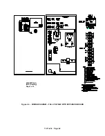
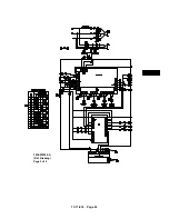
Страница 43: ...13 11 614 Page 43 303EWF546 A Ref Drawing Page 2 of 2 ...
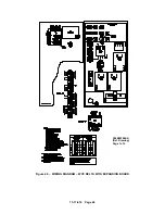
Страница 44: ...13 11 614 Page 44 Figure 4 5 WIRING DIAGRAM WYE DELTA WITH EXPANSION BOARD 304EWF546 A Ref Drawing Page 1 of 2 ...
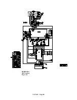
Страница 45: ...13 11 614 Page 45 304EWF546 A Ref Drawing Page 2 of 2 ...
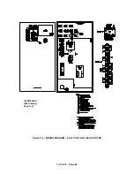
Страница 46: ...13 11 614 Page 46 Figure 4 6 WIRING DIAGRAM FULL VOLTAGE LESS STARTER 305EWF546 A Ref Drawing Page 1 of 2 ...
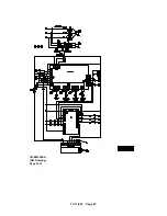
Страница 47: ...13 11 614 Page 47 305EWF546 A Ref Drawing Page 2 of 2 ...

