13-11-614 Page 61
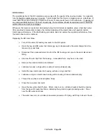
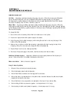
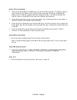
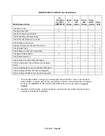
Every 125 Hours Operation
1.
Check for dirt accumulation on oil/aftercooler core faces and the cooling fan. If cleaning is required,
clean the exterior fin surfaces of the cores by blowing compressed air carrying a nonflammable
safety solvent in a direction opposite that of the cooling fan air flow. This cleaning operation will
keep the exterior cooling surfaces clean and ensure effective heat dissipation.
2.
Check the airend reservoir oil level - add oil if required. Loss of oil will be because of seal failure or
leaks in the system and should be fixed immediately.
3.
Check the level of condensate in the control air filter bowl. Use the manual pet cock to evacuate any
accumulation and check the operation of the automatic float valve. Cleanse the automatic float valve
as needed.
4.
Check the quality of the raw (incoming), RO (treated) and injection (reservoir) water. Refer to
Section 8, for recommendations to check the water quality.
Every 500 Hours Operation
1. Check the delivery of filtered water from the reverse osmosis system.
Refer to the RO Filtration System, SECTION 8, “Monitoring the Water Flow”, for the recommended
procure.
Every 2000 Hours Operation
1.
Change the airend lubricant. UNDER ADVERSE CONDITIONS, CHANGE MORE FREQUENTLY
(refer to “Oil Change Interval” in Section 5). Flush reservoir if required. DO NOT MIX
LUBRICANTS.
Every Year
1. Check the relief valve for proper operation. See Section 4, page 38.
Содержание ROTORCHAMP EWF99C-100
Страница 7: ...13 11 614 Page 7 Figure 1 2 PACKAGE ILLUSTRATION AIR COOLED 309EWF797 A Ref Drawing ...
Страница 8: ...13 11 614 Page 8 Figure 1 3 PACKAGE ILLUSTRATION WATER COOLED 310EWF797 A Ref Drawing ...
Страница 9: ...13 11 614 Page 9 Figure 1 4 AIR COOLED SCHEMATIC 307EWF797 A Ref Drawing ...
Страница 10: ...13 11 614 Page 10 Figure 1 5 WATER COOLED SCHEMATIC 308EWF797 A Ref Drawing ...
Страница 29: ...13 11 614 Page 29 Figure 4 2 FLOW CHART FOR SETUP PROGRAMMING 300EWC1255 Ref Drawing ...
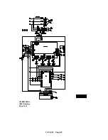
Страница 43: ...13 11 614 Page 43 303EWF546 A Ref Drawing Page 2 of 2 ...
Страница 44: ...13 11 614 Page 44 Figure 4 5 WIRING DIAGRAM WYE DELTA WITH EXPANSION BOARD 304EWF546 A Ref Drawing Page 1 of 2 ...
Страница 45: ...13 11 614 Page 45 304EWF546 A Ref Drawing Page 2 of 2 ...
Страница 46: ...13 11 614 Page 46 Figure 4 6 WIRING DIAGRAM FULL VOLTAGE LESS STARTER 305EWF546 A Ref Drawing Page 1 of 2 ...
Страница 47: ...13 11 614 Page 47 305EWF546 A Ref Drawing Page 2 of 2 ...

