


13-11-614 Page 41
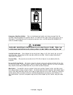
Emergency Stop/Push Button
- This is a maintained push-button, and removes power from the
controller outputs regardless of controller status. It is located on the upper section of the panel, next to
the keypad. This should be used for emergency purposes only - use the keypad [STOP/RESET] for
normal controlled stopping.
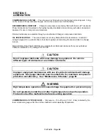
WARNING
Automatic restarting or electrical shock can cause injury or death. Open, tag
and lockout main disconnect and any other circuits before servicing the unit.
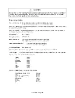
Control Transformer
- This changes the incoming power voltage to 110-120 volts for use by all unit
control devices. Two primary and one secondary fuse are provided. Refer to adjacent labeling for
replacement information.
Terminal Strip
- This provides connections for all 110-120 volt devices not contained within the
enclosure.
Fan and Oil Pump Starter
- The starter is used to provide control and overload protection for the fans
and oil pump motors. Overload heaters should be selected and adjusted based on the motor nameplate
amps and the instructions located inside the cover of the electrical enclosure.
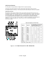
Main Starter
- This starter is used to provide control and overload protection for the main drive motor.
Full voltage starters employ a single contactor. Overload heaters should be selected and adjusted based
on the motor nameplate amps and the instructions located inside the cover of the enclosure. Wye-Delta
starters employ three contactors which are controlled sequentially to provide low current starting. For
Wye-Delta starters, the motor nameplate amps must be first multiplied by 0.577 before using the heater
table.
Содержание ROTORCHAMP EWF99C-100
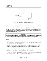
Страница 7: ...13 11 614 Page 7 Figure 1 2 PACKAGE ILLUSTRATION AIR COOLED 309EWF797 A Ref Drawing ...
Страница 8: ...13 11 614 Page 8 Figure 1 3 PACKAGE ILLUSTRATION WATER COOLED 310EWF797 A Ref Drawing ...
Страница 9: ...13 11 614 Page 9 Figure 1 4 AIR COOLED SCHEMATIC 307EWF797 A Ref Drawing ...
Страница 10: ...13 11 614 Page 10 Figure 1 5 WATER COOLED SCHEMATIC 308EWF797 A Ref Drawing ...
Страница 29: ...13 11 614 Page 29 Figure 4 2 FLOW CHART FOR SETUP PROGRAMMING 300EWC1255 Ref Drawing ...
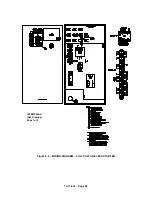
Страница 43: ...13 11 614 Page 43 303EWF546 A Ref Drawing Page 2 of 2 ...
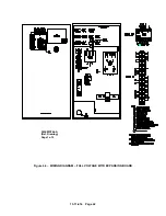
Страница 44: ...13 11 614 Page 44 Figure 4 5 WIRING DIAGRAM WYE DELTA WITH EXPANSION BOARD 304EWF546 A Ref Drawing Page 1 of 2 ...
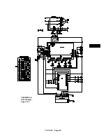
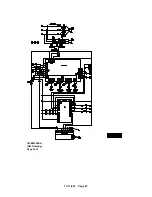
Страница 45: ...13 11 614 Page 45 304EWF546 A Ref Drawing Page 2 of 2 ...
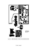
Страница 46: ...13 11 614 Page 46 Figure 4 6 WIRING DIAGRAM FULL VOLTAGE LESS STARTER 305EWF546 A Ref Drawing Page 1 of 2 ...
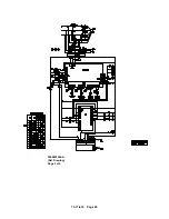
Страница 47: ...13 11 614 Page 47 305EWF546 A Ref Drawing Page 2 of 2 ...


