7 Troubleshooting and after-sales services
7.2 Troubleshooting and debugging
95
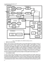
1st local oscillation VCO ring. The 2nd local oscillator frequency is fixed at 5085MHz and 1835MHz.
Signal acquisition and processing module
The signal acquisition and processing module has two main parts: signal acquisition and signal
processing. The signal acquisition part is mainly composed of amplifier, anti-alias filter, high-speed ADC,
sampling clock generation circuit and other parts, which completes the functions of amplification, filtering
and high-speed sampling of 140MHz IF signal. The signal processing part is mainly composed of FPGA,
CPU and other parts. FPGA is responsible for digital signal extraction and filtering, real-time FFT
calculation, real-time demodulation, etc. CPU is reponsible for level and spectrum calculation, display
processing, and process control of the whole machine.
Display module
The display module contains two parts: touchscreen and LCD, with a large 10.1-inch display and support
for full touch operation.
7.2 Troubleshooting and debugging
Under normal circumstances, the problem with the instrument is due to hardware, software, or improper
use of users. Once a problem occurs, first observe the error message and save it. Then, analyze the
possible causes and refer to the methods provided in section
7.2.1 "Basic Troubleshooting Process" and
section 7.2.2 "Common Fault Symptoms and Debugging Methods"
to check and solve the problem in
advance. You can also
contact our service center and provide the error messages you‘ve collected, and
we will coordinate with you to solve the problem as soon as possible. For details, please refer to the
contact information provided in this manual, or check online at
support service point.
Troubleshooting and instructions
This section introduces the way on how to judge and handle failures (if any) of the 3943B monitoring
receiver, and feed them back to the manufacturer as accurately as possible if necessary for quick
solution.
Basic troubleshooting process
Common fault phenomena and troubleshooting methods
7.2.1 Basic troubleshooting process
When there is a problem with the instrument, first check the following:
If the 3943B monitoring receiver cannot be started after pressing the start button, please check
whether the power supply is normal and whether the adapter indicator is on or whether the battery
level is normal.
If there is nothing abnormal, please check whether the test tool and test environment meet the
requirements, whether the test port connector is damaged and whether the calibration parts
performance indicators are normal.
In case of any other instrument, cable or connector connected with the monitoring receiver properly
and run normally.
If the monitoring receiver cannot communicate over the LAN, check the yellow LED next to the LAN
connector on the side panel, if the light does not blink, check the LAN cable and connections.
Does the instrument display an error message? If there are error messages, please refer to section
"7.3 Error Messages" in this manual.
7.2.2 Common fault phenomena and troubleshooting methods
The following lists the common faults and troubleshooting methods as per function types.
Tip
Содержание 3943B
Страница 2: ...3943B Monitoring Receiver User s Manual Ceyear Technologies Co Ltd...
Страница 4: ......


