8 Technical indicators and testing methods
8.5 Performance characteristics test
106
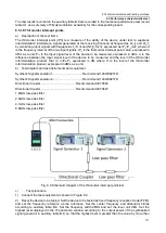
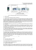
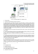
Fig. 8.3 Schematic diagram of input port SWR test
c) Test procedure
1) Set the frequency range and output power of the vector network analyzer as appropriate
parameters and select the SWR display.
2) Single-port reflection measurement calibration (including open-circuit, short-circuit, and load
calibration) for vector network analyzers.
3) After completing the calibration, remove the calibration piece from the vector network analyzer.
Connect the test equipment according to Fig. 8.3 and connect the test port to the input port of the device
to be tested.
4) Reset the device to be tested. Set the device to be tested to fixed frequency reception mode (FFM).
Set the center frequency in order according to the auxiliary table B.3 and set the attenuator off.
5) In the frequency band from 9 kHz to 1.5 GHz, the voltage standing wave ratio (VSWR) of the
corresponding frequency point of the device to be tested is read out using the frequency scale function of
the vector network analyzer and recorded in the auxiliary table B.3.
6) In the 1.5GHz to 8GHz band, use the frequency scale function of the vector network analyzer to
read out the maximum voltage VSWR in the band corresponding to the frequency point of the
corresponding equipment to be tested and record it in the auxiliary table B.3.
d) Recording and data processing
The maximum value of the voltage SWR of the corresponding frequency band in the auxiliary table B.3 is
summarized and recorded in the functional performance test record table A.1.
8.5.1.4 Display average noise level (spectrum channel)
a) Description of the test items
Measure the reception sensitivity of the spectrum channel of the device to be measured in different
frequency bands. Use the frequency scale function to locate the frequency point with the worst reception
sensitivity in each band, then read out the noise level value at that frequency point and normalize it to the
1Hz resolution bandwidth. In the measurement, if there is a residual response frequency point, the
residual response frequency point should be removed.
b) Test equipment
50Ω load
3.5mm(f)-N type(m) connector
Содержание 3943B
Страница 2: ...3943B Monitoring Receiver User s Manual Ceyear Technologies Co Ltd...
Страница 4: ......


