7 Troubleshooting and after-sales services
7.1 Working principles
94
Preselector
Amplifier
Attenuator
Sw
itc
h
2 LO
Time
base
Reference
Loop
Decimal
Loop
VCO
Sampling
Loop
Amplifier
Filter
A/D
Sampling
Clock
CPU
Battery
Management
FPGA
Amplifier
Filter
20MHz~3.6GHz
Preselector Converter
Module
LO Module
Acquisition
and processing
module
LCD Module
Input
1 LO
112MHz
3.6GHz~8GHz
LPF
Preselector
Amplifier
Filter
9kHz~30MHz
Amplifier
Display
Interface
Touch Screen
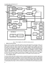
Fig. 7.1 Block diagram of the 3943B monitoring receiver
Optional inverter module
After the antenna sends the received RF signal to the pre-selected frequency conversion module, it is
switched by the microwave switch to 3 bands: 0-band (9 kHz to 30 MHz), 1-band (20 MHz to 3.6 GHz)
and 2-band (3.6 GHz to 8 GHz). Among them, the 0-band low-pass filter is directly output to the
acquisition and processing module, and the 1-band signal is amplified or attenuated and mixed with a
local oscillator from 5245MHz to 8825MHz to obtain a 5225MHz IF signal, which is amplified and filtered
and mixed with a second local oscillator with a fixed frequency of 5085MHz to produce a 140MHz
second IF. After amplification and filtering, the 2-band signal is mixed with the local oscillator from
1625MHz to 6025MHz to obtain the first IF signal of 1975MHz, and after amplification and filtering, it is
mixed with the second local oscillator of fixed frequency 1835MHz to produce the second IF of 140MHz.
The two IF signals are selected by a switch and output to the acquisition and processing module.
Local oscillator module
The main function of the local oscillator module is to provide the required local oscillator signal for the
pre-selected inverter module, including the 1st and 2nd local oscillators. In this project, the 1st oscillator
is obtained by fast digital sweep technique, which can improve the detection speed of electromagnetic
signals, and at any frequency point. The 1st oscillator is a frequency synthesized local oscillation signal.
The synthesized local oscillation signal is obtained by the phase-locked sweep method, which consists
of several phase-locked rings, such as the reference ring, the fractional ring, the sampling ring and the
Содержание 3943B
Страница 2: ...3943B Monitoring Receiver User s Manual Ceyear Technologies Co Ltd...
Страница 4: ......


