8 Technical indicators and testing methods
8.5 Performance characteristics test
113
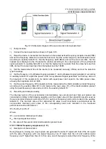
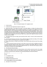
Fig. 8.10 Schematic diagram of the second-order intercept point test
c) Test procedure
1) Connect the test equipment as shown in Figure 8.10.
2) Reset the device to be tested. Set the device to be tested as fixed frequency reception mode (FFM)
and set the frequency reference as external reference. Set the center frequency and attenuator status
according to auxiliary table B.10. Set the frequency width 2MHz and set the level unit dBm. Set the
highest level displayed in the IF panorama window according to the output power of the synthesized
signal generator in auxiliary table B.10, so that the highest level is greater than the value by more than
3dB, and set the lowest level less than the highest level by 100dB.
3) Set the measurement time of the device to be measured manually, 350ms, and set the detection
type to average.
4) Set the frequency of synthesized signal generator 1 and synthesized signal generator 2 according
to auxiliary table B.10, adjust the power of the two synthesized signal generators so that they arrive at
the input port of the equipment to be tested with equal power and equal to the table power value,
allowing the magnitude error ±0.5dB.
5) Set the center frequency of the equipment to be measured as the intermodulation product frequency
according to the auxiliary table B.10, and measure the level value (P
t
) of the intermodulation product
using the peak frequency scale and record it in the auxiliary table B.10.
d) Recording and data processing
The intercept points of the second-order intermodulation low end product and high end product are
calculated according to the following equation, and the smaller value of the calculation result is used as
the second-order intercept point value (IP
2
) for each test frequency point and recorded in the auxiliary
table B.10. The minimum value of the calculated IP
2
value in each test band is summarized as the
second-order intercept point value of the corresponding band and recorded in the functional
performance test record table A.1.
IP
2
=P
in
+(P
in
-P
t
)=2P
in
-P
t
..........................................
(
5
)
Where:
IP
2
- second-order intercept point value
;
P
in
- the input signal level value;
P
t
- the value of the second-order intermodulation product level.
8.5.1.11 Mirror frequency suppression (1 IF)
a) Description of the test items
During frequency mixing, two input signals can generate the same IF signal with that of the LO signal
with the same frequency, with one signal frequency one IF lower than the LO and another signal
frequency one IF higher than the LO. In this case, one of the signal is called the mirror frequency of the
Содержание 3943B
Страница 2: ...3943B Monitoring Receiver User s Manual Ceyear Technologies Co Ltd...
Страница 4: ......


