3 Quick Start
3.2 Description of front and rear panels and interfaces
23
①
② ③
④
⑤
⑥
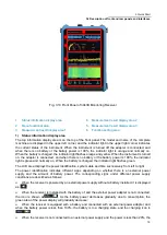
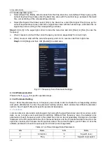
Fig. 3.14 Top Panel of 3943B
1. 10MHz input/output
2. External trigger input
3. GNSS antenna
4. AUX interface
5. 140MHz
intermediate
frequency output
6. RF input
1) 10MHz input/output
The 10MHz signal of other equipment can be externally connected as the reference signal of the
receiver. The 10MHz reference signal output function in the receiver is temporarily not supported.
2) External trigger input
The 3943B monitoring receiver can be set to the external trigger mode. The external trigger source is
connected to the trigger input port of the receiver, and the output range of the source should be -5V~+5V.
It can be set by the program whether it is triggered by rising edge or falling edge.
3) GNSS antenna
It is the antenna equipment connected with GNSS, which can be used to locate and time the current
position of the receiver.
4) AUX interface
It is the communication interface between receiver and external devices such as antenna, and the pins
of AUX interface are defined as follows.
Table 3.7 Definitions of AUX Interface Pins
Pin
1
2
3
4
5
6
7
Function
5V output
Maximum
500mA
I/O
I/O
Grounding
Serial
port
TXD
Serial
port
RXD
Antenna
trigger
input
Direction
Output
In/out
In/out
--
Output
Input
Input
5) 140MHz intermediate frequency output
It can provide intermediate frequency signal output through software configuration for external
equipment.
6) RF input
It is used for the input of the measured signal.
Содержание 3943B
Страница 2: ...3943B Monitoring Receiver User s Manual Ceyear Technologies Co Ltd...
Страница 4: ......


