3 Quick Start
3.2 Description of front and rear panels and interfaces
20
battery is in an undervoltage state, and the icon is shown as
. When such an icon appears,
please charge the battery in time.
Setting and modification of system date and time: set by pressing [
] → [setting] → [general setting]
→ [date/time setting] in the lower left corner.
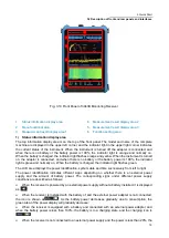
2) Menu functional area
Menu functional area buttons are used for setting common functions, as shown in Table 3.6.
Table 3.6 Description of Menu Functional Area
Key name
Functional description
Demodulation
bandwidth
Set the demodulation bandwidth, which can be set as 100Hz, 150Hz, 300Hz, 600Hz,
1kHz, 1.5kHz, 2.1kHz, 2.4kHz, 2.7kHz, 3.1kHz, 4kHz, 4.8kHz, 6kHz, 9kHz, 12kHz,
15kHz, 30kHz, 50kHz, 120kHz, 150kHz, 250kHz, 300kHz, 500kHz, 800kHz, 1MHz,
1.25MHz, 1.5MHz, 2MHz, 5MHz, 8MHz, 10MHz and 20MHz.
Demodulation
mode
Set the demodulation mode, which can be set as AM, FM, I/Q, PULSE, LSB, USB, CW
and ISB.
Detector
Mode
Maximum peak value, mean value, power and sampling.
Attenuation
control
Set the attenuator state, turn on and off or automatically control the attenuator.
Gain control
Set the gain control status, manually set the gain or automatically control the gain
according to the signal.
Squelch level
Set the squelch level, which only works when squelch is turned on.
Howling
Set the howling switch. When the howling is on, you can set the level value to adjust the
tone.
Audio switch
Set the demodulating sound switch.
Screen lock
Lock the screen to prevent misoperations.
Reset
Factory reset, reset before shutdown, user reset and other operations.
Screenshot
Save the screen measurement results as pictures in .png format.
3) Measurement result display area 1
In the current setting state, the measurement result of level field strength is displayed in display area 1.
4) Measurement result display area 2
In the current setting state, the intermediate frequency panoramic measurement results are displayed in
display area 2.
5) Measurement result display area 3
In the current setting state, the measurement results of the intermediate frequency waterfall are
displayed in display area 3.
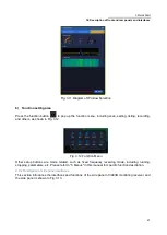
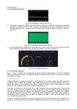
The display contents of the above three windows can be switched among level field strength,
intermediate frequency panorama, intermediate frequency waterfall, radio frequency panorama and
radio frequency waterfall, or two windows can be selected for display, which can be switched by
[Parameter] → [Window Selection], as shown in Fig. 3.11.
Содержание 3943B
Страница 2: ...3943B Monitoring Receiver User s Manual Ceyear Technologies Co Ltd...
Страница 4: ......

