8 Technical indicators and testing methods
8.5 Performance characteristics test
117
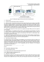
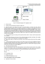
Fig. 8.13 Schematic diagram of IF suppression test
c) Test procedure
1) Connect the test equipment as shown in Figure 8.13.
2) Reset the device to be tested. The device to be tested shares a common time base with the
synthesized signal generator, and the frequency reference of the device to be tested is set as the
external reference. Set the device to be tested to fixed frequency reception mode (FFM mode). In the IF
Panorama window, set the bandwidth to 100 kHz and the resolution bandwidth (RBW) to auto. Set the
center frequency and attenuator status according to auxiliary table B.13. Set the level unit to dBm. Set
the display maximum level according to the output power of the synthesized signal generator, so that the
maximum level is greater than the value by 3dB or more, and set the minimum level less than the
maximum level by 100dB.
1) Set the detection type to average, the measurement time mode to manual, and the measurement
time to 350ms.
2) Set the output frequency and power of the synthesized signal generator according to the auxiliary
table B.13, which is the IF frequency of the equipment to be tested.
3) Use a power meter to measure the input power of the IF signal and record the value in the auxiliary
table B.13.
4) In the IF panorama window of the device to be tested, the level value of the IF interference signal is
measured using the frequency scale and the value is recorded in the auxiliary table B.13. If the IF
interference signal level does not exceed the background noise by 10 dB, the center frequency position
level value is recorded in the auxiliary table B.13.
d) Recording and data processing
Process the test data according to the following formula and record the calculation results in the auxiliary
table B.13. The minimum value of the calculated IF suppression ratio in each band is recorded as the
summary of IF rejection ratio in this band in the functional performance test record table A.1.
R
IF
= P
in
− P
IF
.............................................
(
8
)
Where:
R
IF
: IF suppression ratio.
P
in
: iF signal input power.
P
IF
: IF interference signal level value.
8.5.1.14 Re-radiation of the local oscillation
a) Description of the test items
Содержание 3943B
Страница 2: ...3943B Monitoring Receiver User s Manual Ceyear Technologies Co Ltd...
Страница 4: ......

