8 Technical indicators and testing methods
8.5 Performance characteristics test
109
recorded in the auxiliary Table B.6.
d) Recording and data processing
The data in Auxiliary Table B.6 are processed according to the following formula, and the calculation
results are recorded in Auxiliary Table B.6 and the values of positive and negative frequency deviation
phase noise difference at each frequency point are summarized and recorded in Functional
Performance Test Record Table A.1.
8
.
0
log
10
RBW
P
f
L
Δ
m
..................................
(
3
)
Where:
L(fm) - is the sideband noise.
P
Δ
- is the relative frequency scale magnitude.
RBW - is the resolution bandwidth.
8.5.1.7 AM demodulation sensitivity
a) Description of the test items
This test is to examine the AM audio demodulation sensitivity of the device to be tested, using the ITU-R
SM.1840 proposal method. The device to be tested has AM demodulation function, providing a total of
34 demodulation bandwidths in the range of 100Hz to 20MHz. This test uses a synthesized signal
generator to generate an AM signal, the device to be tested performs AM demodulation of the signal,
and then tests the demodulated signal output from the headphone interface of the device to be tested.
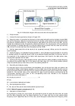
b) Test diagram and test instruments and equipment
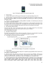
Synthetic Signal Generator ....................................... Recommend 1464/E8257D
Audio analyzer ........................................... Recommend U8903A/U8903B
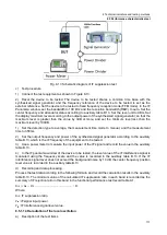
Fig. 8.7 Schematic diagram of AM demodulation sensitivity test
c) Test procedure
1) Connect the test equipment according to Fig. 8.7, the equipment to be tested and the synthesized
signal generator common time base; the headphone interface of the equipment to be tested is
connected to the input channel interface of the audio analyzer.
2) According to the auxiliary table B.7 of the test frequency set synthetic signal generator frequency,
power -70dBm, select AM modulation, set the modulation rate of 1kHz, modulation depth of 50%.
3) Reset the device to be tested. Set the device to be tested to fixed frequency reception mode (FFM),
set the center frequency according to the test frequency of auxiliary table B.7, set the frequency width to
50kHz, demodulation mode to AM, demodulation bandwidth to 6kHz, attenuator off, gain control select
AGC, audio output on.
4) Select the analysis channel of the audio analyzer, set the measurement function of Function1 to
frequency, set the measurement function of Function2 to "SINAD" mode, set the weighting option of the
filter function (Filter) in the measurement configuration (Meas. Weighting) option in the filter function
(Filter) of the measurement configuration (Meas. Config) is set to "CCITT", adjust the output power of the
Содержание 3943B
Страница 2: ...3943B Monitoring Receiver User s Manual Ceyear Technologies Co Ltd...
Страница 4: ......


