43
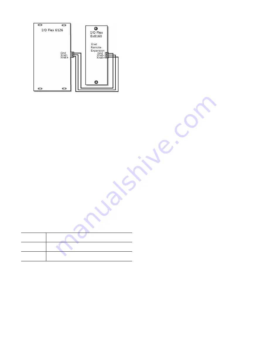
Fig. 32 — Flex and Expansion XNET Connection
Sequence of Operation, VAV Units Only
50BVJ,W
See the integration points list on page CL-1 for specific points and
values.
CONTROL SOURCE (RUN CONDITIONS)
The unit may have external or internal control sources to initiate
heating or cooling operation.
EXTERNAL CONTROL SOURCE
The unit may be controlled from the following external sources:
• Digital input
• BAS – Building Automation System
• Manual on
DIGITAL INPUT
Provides a method of running the unit by providing a contact clo-
sure (On/Off) to UI-12. Digital input provides a simple interface
for enabling unit operation. Once enabled, the unit will run until
the occupied set point has been satisfied.
BAS
Provides a network interface to the heat pump. The I/O Flex 6126
controller supports the following building automation protocols
(see Table 21):
MANUAL ON
Places the unit in manual run mode; the unit will operate until the
set point is satisfied.
INTERNAL CONTROL SOURCE (KEYPAD)
All controllers are provided with a battery backup real time clock.
When configured for Keypad, the internal scheduler uses the local
time and user schedule to initiate unit operation. Occupied Sched-
ule: 56°F supply air set point (adjustable).
Unit Mode
50BV VAV units are configured with DX cooling and modulating
HGRH. The selected unit mode in the 50BV controller should be
Discharge Air control. Other modes are not applicable and can
cause operational issues.
Fan Modes
The Fan mode option is used to select the type of fan hardware be-
ing used with the unit. Fan hardware is application specific and
will determine the behavior for the specific application for which
it is being applied.
The Fan option may be configured with one of the following op-
tions:
• Supply Air Fan (SAF) Start/Stop (also known as On/Off
signaling)
• Variable Frequency Drive (or Variable Fan used in VAV
applications)
• Return Fan interlock with Supply Fan (If SAF runs RAF
runs)
START/STOP FANS
The fan enable signal is provided on BO-1 of the I/O Flex 6126
controller; operation is interlocked with cooling and re-heat opera-
tions. The return air fan can be enabled via the BACview tool, and
it will be commanded 5 seconds after the supply fan has been en-
gaged at all times.
The supply fan can also be set to stop if the return fan is in alarm
via the BACview tool.
VARIABLE FREQUENCY DRIVE (VFD) FAN
The VFD uses an analog signal (0 to 10V) to control the speed of
the blower. This signal is output from Analog Output 1 (AO-1) of
the I/O Flex 6126 controller.
The supply and return air fan speeds are modulated by indepen-
dent PID loops to maintain independent static pressure set points;
the factory-provided duct static pressure sensor is required as input
(connected to UI 11 for supply and IN-10 for return) on the I/O
Flex 6126 controller and the I/O Flex EX8160 expander, for the
VFD blower option. Units do not allow for mounting of the Re-
turn Fan VFD inside the equipment and require the VFD equip-
ment to be mounted close to the unit. An inside wall in the me-
chanical room close to the unit is typically used for mounting an
external VFD. See Table for VFD factory default settings.
SUPPLY AND RETURN FAN OPERATION
When the unit control is set for occupied operation the fan will run
continuously as the default behavior. If the return fan is enabled, it
will follow the operation of the supply fan mode which may be
modified to cycle only during mechanical operation. During unoc-
cupied operation the fan will only cycle during a call to maintain a
cooling set point.
FAN OPERATION DURING DISCHARGE (SUPPLY AIR
TEMPERATURE) AIR CONTROL (DAC)
For DAC applications, the fan’s speed is calculated as a demand
percent calculated based on the PID static pressure sensor value
and the static pressure set point.
If static pressure reset strategies are utilized the minimum fan
speed recommended is 40% of nominal CFM. If the fan demand
is less than 40% of nominal CFM (20% for the return fan) the
PID loop will be disregarded and the fan will run at the mini-
mum value.
Units configured for discharge air control will run only when the
controller is in occupancy mode.
Table 21 — Communication Protocol
BACnet
Building Automation and Control network
Modbus
Common open industrial protocol standard
LonWorks
LonWorks Automation and control network
(Card required)
Содержание Omnizone 50BVC
Страница 9: ...9 Fig 5 Low Boy Field Split 40 60 Ton 1 3 2 4 1 2 3 4...
Страница 36: ...36 Fig 27 UPM Sequence of Operation SOO Flow Chart...
Страница 42: ...42 Fig 31 I O Flex 6126 Controller Input Modes and Diagram...
Страница 89: ......


