


6
required. Use the ENTER and arrow keys to enter the four dig-
its of the password. The default password is 1111.
Pressing the ESCAPE and ENTER keys simultaneously will
scroll an expanded text description across the display indicating
the full meaning of each display point. Pressing the ESCAPE
and ENTER keys when the display is blank (MODE LED level)
will return the display to its default menu of rotating AUTO
VIEW display items. In addition, the password will need to be
entered again before changes can be made.
Changing item values or testing outputs is accomplished in the
same manner. Locate and display the desired item. If the dis-
play is in rotating auto-view, press the ENTER key to stop the
display at the desired item. Press the ENTER key again so that
the item value flashes. Use the arrow keys to change the value
of state of an item and press the ENTER key to accept it. Press
the ESCAPE key and the item, value or units display will re-
sume. Repeat the process as required for other items.
There are some points that can be forced from the scrolling
marquee or the Navigator display. If the user needs to force a
variable, follow the same process as when editing a configura-
tion parameter. A forced variable, regardless where the force
has come from will be displayed with a blinking “.” on a scroll-
ing marquee and a blinking “f” on a Navigator display follow-
ing its value. For example, if economizer commanded position
(
EC.CP
) is forced, the Navigator display shows “80f”, where
the “f” is blinking to signify a force on the point. The scrolling
marquee display shows “80.” Where the “.” is blinking to sig-
nify a force on the point. Remove the force by selecting the
point that is forced with the key ENTER and then pressing the
up and down arrow keys simultaneously. Depending on the
unit model, factory-installed options and field-installed acces-
sories, some of the items in the various Mode categories may
not apply.
System Pilot™ and Touch Pilot™ Devices
The System Pilot device (33PILOT-01) and Touch Pilot device
(33CNTPILOT) can be used as CCN communication user-in-
terfaces. These devices can be put on the CCN bus and ad-
dressed to communicate with any other device on the network.
Unlike the scrolling marquee and Navigator display, these pi-
lots read the unit’s CCN tables and its CCN points can be mon-
itored, forced, or configured. The Pilot devices can be used to
install and commission a 3V zoning system, linkage compati-
ble air source, universal controller, and all other devices oper-
ating on the Carrier communicating network.
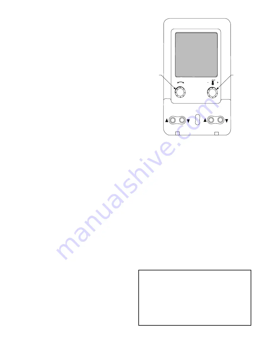
Additionally, the System Pilot device can serve as a wall-mount-
ed temperature sensor for space temperature measurement. The
occupant can use the System Pilot device to change set points. A
security feature is provided to limit access of features for unau-
thorized users. See Fig. 3 for System Pilot device details.
CCN Tables and Display
In addition to the unit-mounted scrolling marquee display, the
user can also access the same information through the CCN ta-
bles by using the Service tool or other CCN programs/devices.
The variable names used for the CCN tables and the scrolling
marquee menus may be different and more items may be dis-
played in the CCN tables. Details on the CCN tables are in-
cluded with the local display menus in Appendix A. Appendix
A is structured towards the organization of the local display
(scrolling marquee) menus. Because of the variety of CCN
programs and devices, the CCN tables, sub-tables, and points
are referenced within that organization.
Fig. 3 — System Pilot User Interface
Force Hierarchy
There is a hierarchy in CCN with regards to forcing a point.
Programs and devices write a force at different priority levels.
A higher level (smaller number, 1 being the highest) will over-
ride a lower level force. The scrolling marquee uses a Control
Force at level 7. The Navigator writes a Service Force which is
level 3. System Pilot and Touch Pilot devices write Supervisor
Forces at level 4. Network programs can be set to write differ-
ent level priority forces.
Generic Status Display Table
The GENERIC points table allows the service/installer the
ability to create a custom table in which up to 20 points from
the 5 CCN categories (Points, Config, Service-Config, Set
Point, and Maintenance) may be collected and displayed.
In the Service-Config table section, there is a table named
“GENERICS.” This table contains placeholders for up to 20
CCN point names and allows the user to decide which points
are displayed in the GENERIC points sub-table under the sta-
tus display table. Each one of these placeholders allows the in-
put of an 8-character ASCII string. Using a CCN interface, en-
ter the Edit mode for the Service-Config table “GENERICS”
and enter the CCN name for each point to be displayed in the
custom points table in the order they will be displayed. When
done entering point names, download the table to the rooftop
unit control.
IMPORTANT: The computer system software (Comfort-
VIEW, Service Tool, etc.) that is used to interact with CCN
controls, always saves a template of items it considers as
static (e.g., limits, units, forcibility, 24-character text
strings, and point names) after the software uploads the
tables from a control. Thereafter, the software is only con-
cerned with run time data like value and hardware/force sta-
tus. With this in mind, it is important that anytime a change
is made to the Service-Config table “GENERICS” (which
in turn changes the points contained in the GENERIC point
table), that a complete new upload be performed.
S
CROLL
+
-
NAVIGATE/
EXIT
MODIFY/
S
ELECT
PAGE
Содержание /50HC 04-28
Страница 61: ...61 Fig 21 Saturated Condensing Temperature Thermistor Location 48 50HC 14 SCT B SCT A CIRCUIT B CIRCUIT A ...
Страница 69: ...69 Fig 24 Typical Control Diagram for 48HC 04 14 Units 48HC 08 09 shown ...
Страница 70: ...70 Fig 25 Typical Power Diagram for 48HC 04 14 Units 48HC 08 09 shown ...
Страница 71: ...71 Fig 26 Typical Control Diagram for 50HC 04 14 Units 50HC 14 shown ...
Страница 72: ...72 Fig 27 Typical Power Diagram for 50HC 04 14 Units 50HC 14 Non Humidi MiZer shown ...
Страница 73: ...73 Fig 28 Typical Control Diagram 48HC 17 28 Units ...
Страница 74: ...74 Fig 29 Typical Control Diagram 50HC 17 28 Units ...
Страница 75: ...75 Fig 30 Typical Humid MiZer Power Diagram and Component Arrangement 48 50HC 17 28 Units ...
Страница 76: ...76 Fig 31 Typical Non Humid MiZer Power Diagram and Component Arrangement 48 50HC 17 28 Units ...
Страница 89: ...89 Fig 42 Modulating ERV Wiring Schematic ...
Страница 90: ...90 Fig 43 EnergyX ERV Control Box Component Layouts ...
Страница 101: ...101 Fig 59 Exhaust Fan Assembly Removal Exhaust Fan Assembly ...
Страница 141: ......