62-11640
8–12
An air cleaner service indicator is connected to the
intake manifold. Its function is to indicate when the air
cleaner filter element requires replacement. During
operation: when a plugged filter element causes the
intake manifold pressure to drop to 20” (500 mm) WG,
the indicator will move to the red line. The filter element
should then be replaced and the indicator reset by
pressing the reset button.
1. Ensure the unit will not start automatically by
disabling any two way communication and plac-
ing the STOP/RUN-OFF switch in the OFF posi-
tion. Disconnect the high voltage source and
lockout/tagout the receptacle.
2. Check all connections for mechanical tightness.
Be sure filter outlet pipe is not fractured.
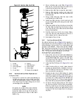
3. Release 2 clips on air cleaner housing and
remove the cover.
4. Remove filter element, wipe inside of air cleaner
housing clean, inspect filter element, and
replace if required.
5. Wipe inside of the cover and re-install.
6. Re-secure 2 clips on air cleaner housing.
7. Start unit and check for leaks. Reset air cleaner
service indicator.
8.5.11
Engine Preheater
The current draw for the preheat circuit is checked
during a Pretrip cycle. Refer to
for amper-
age and resistance values.
a. Troubleshooting The Engine Preheater (EPH):
1. Ensure the unit will not start automatically by
disabling any two way communication and plac-
ing the STOP/RUN-OFF switch in the OFF posi-
tion. Disconnect the high voltage source and
lockout/tagout the receptacle.
2. Disconnect the lead.
3. Measure the resistance between the + terminal
and the heater body. Refer to
correct resistance value.
4. If the resistance is infinite (open) or zero, the
engine preheat element is faulty and must be
replaced.
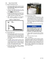
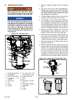
Figure 8.13 Engine Preheater
b. Replacing The Engine Preheater
1. Ensure the unit will not start automatically by
disabling any two way communication and plac-
ing the STOP/RUN-OFF switch in the OFF posi-
tion. Disconnect the high voltage source and
lockout/tagout the receptacle.
2. Remove the inlet hose.
3. Disconnect the lead.
4. Remove the flange, engine preheater, and gas-
kets.
NOTE
To avoid short-circuiting the heater, ensure
that the heater and the heater elements are
vertical when assembling to the intake mani-
fold. The plus terminal is to be mounted
towards the front of the unit.
5. Clean gasket surfaces and reinstall engine pre-
heater and flange using new gaskets. Torque
flange bolts 15 to 20 ft/lbs (20.3 to 27.1 nm).
6. Reconnect the lead.
7. Start unit and run Pretrip to check operation.
8.5.12
Engine Control System
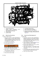
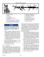
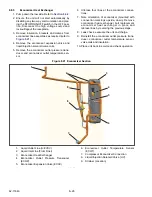
Then engine is controlled by six components (see
): the engine control unit (ENCU), the fuel/
speed actuator (FSA) the engine speed sensor
(ENSSN), the rack position sensor (RPS), the engine
oil pressure switch (ENOPS) and the Engine Coolant
Temperature Sensor (ENCT).
The ENCU starts, stops and controls the speed of the
engine by varying the position of the FSA rod. It also
provides oil pressure, coolant temperature, engine load
and speed signals to the control system via the CAN.
The FSA combines the fuel shutoff solenoid and speed
control solenoid into one component. Opening and
closing the fuel rack (throttle) in accordance with sig-
nals from the ENCU.
The ENSSN provides the speed signal to the ENCU.
The ENOPS is connected to the engine oil pump outlet.
It provides an open or closed signal to the ENCU.
The RPS provides the position of the rack to the ENCU.
The ENCT provides the engine coolant temperature
signal to the ENCU.
If any of these components is not functioning correctly,
the corresponding alarm will be activated.
8.5.13
Rack Position Sensor (RPS) Calibration
The Rack Position Sensor calibration procedure is a
software function that can only be initiated in Techni-
cian Mode. This calibration procedure should be per-
formed after replacing the Engine, the ECU, or the
Rack Position Sensor.
+ TERMINAL
HEATER BODY
Содержание Vector 8500
Страница 23: ...62 11640 1 6 1 3 SAFETY DECALS ...
Страница 24: ...1 7 62 11640 62 03958 ...
Страница 25: ...62 11640 1 8 ...
Страница 26: ...1 9 62 11640 ...
Страница 27: ...62 11640 1 10 ...
Страница 125: ...62 11640 SECTION 6 MESSAGECENTER PARAGRAPH NUMBER Page 6 1 MESSAGECENTER MESSAGES 6 1 ...
Страница 321: ......
Страница 322: ......


