62-11640
5–6
5.2.4
Component Test Mode
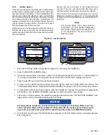
Component Test Mode allows the technician to energize individual circuits for 5 minutes at a time. The unit is not
allowed to start when the System is in Component Test Mode. Instructions for entering the Component Test Mode
are provided in
.
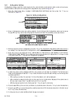
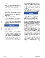
1. Enter the Technicians Menu, highlight COMPONENT TEST MODE and then press the “=” key as described
in
.
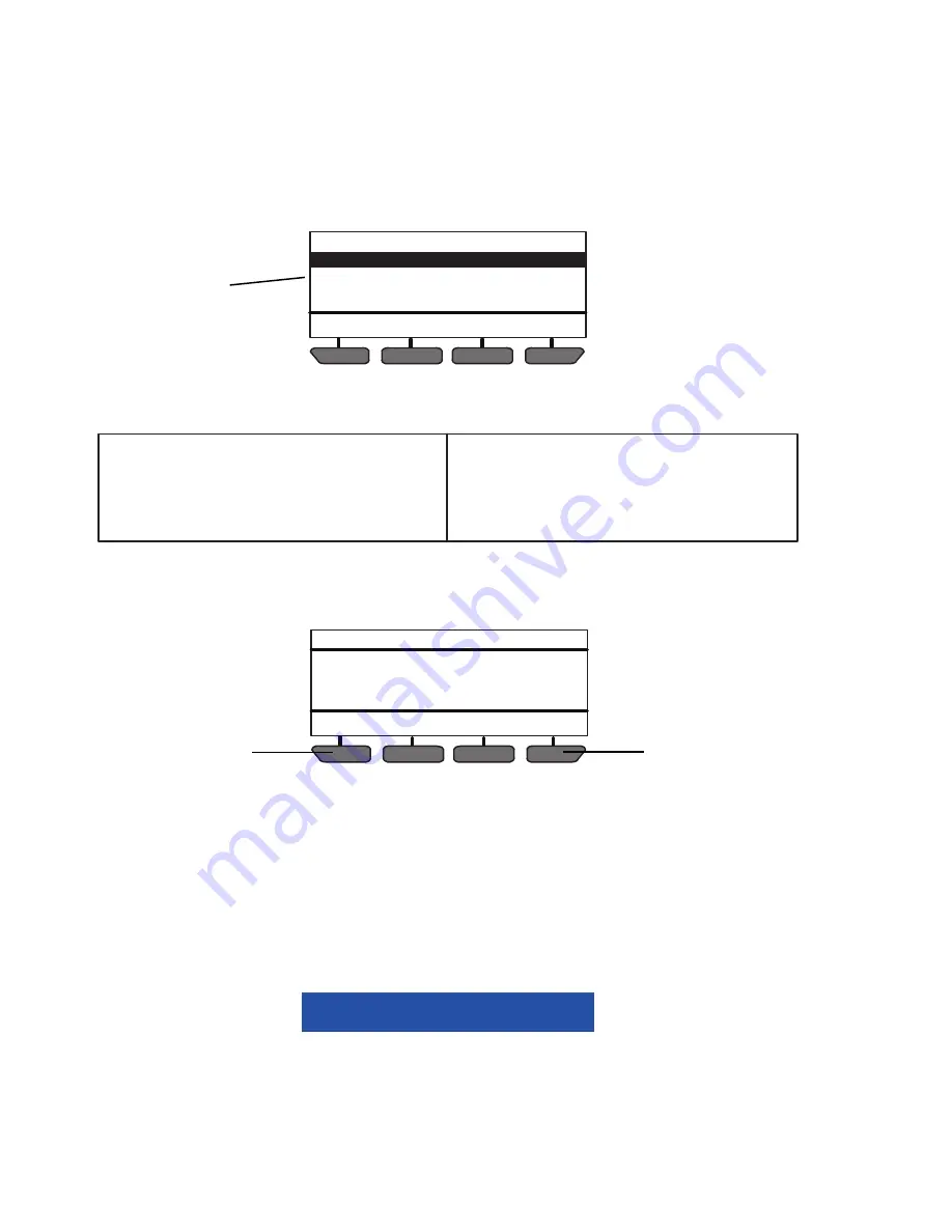
Figure 5.5 Component Test Mode
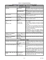
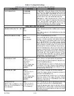
2. The following tests are available. To scroll through the tests press the or - key. The tests will highlight as the
list is scrolled. The available tests include:
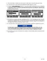
3. With the desired test highlighted, press the “=” key. For example, if BUZZER is selected, the buzzer will
come on, and “BUZZER OFF IN 5 MINUTES” will display. The minutes will count down to 0 at which time
the circuit will be de-energized, and the operator message panel will return to the test selection screen.
4. When a component is energized in Component Test Mode, the AMP DRAW display initially shows the cur-
rent draw of the system, after a few seconds the display will change to reflect the current draw of the system
plus the added component. For example, if CCON is energized in Component Test Mode, the AMP DRAW
display might initially show .75 Amps, then after a few seconds, the AMP DRAW display will change to 1.0
Amps. The difference between the two readings reflects the current draw of the component being tested; in
this case CCON is drawing .25 Amps.
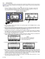
5. To extend the test time, press the RESET TIMER soft key. The time will reset to 5 minutes. To stop the test
press the CANCEL/STOP soft key.
6. Continue as above to test additional components as required.
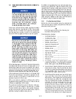
NOTICE
Technician Mode should be canceled when work is complete. If Technician Mode is not can-
celed, Technician Mode will be available for 60 minutes after the last key press without requir-
ing a code, even after placing the SROS in the OFF and then back in the RUN/STOP position.
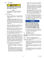
7. Once activity requiring use of Technician Mode is complete, Technician Mode should be manually canceled,
refer to
BACK
EXIT
ENCU POWER CIRCUIT
ENGINE PREHEAT CIRCUIT
BUZZER
LIV
COMPONENT TEST MODE (1 OF 13)
2 & 3
ENCU Power Circuit (MM output @ 3MM9)
Engine Preheat Circuit (MM output @ 3MM14)
Buzzer (MM ground @ 3MM
ï
15)
LIV (MM output @ 3MM
ï
5)
Heater Contactor 1 (2CCB output @ 2CCB
ï
24)
Heater Contactor 2 (2CCB output @ 2CCB
ï
13)
Evaporator Motor Contactor1 (2CCB output @ 2CCB
ï
01)
Power Supply Contactor (1CCB output @ 1CCB
ï
13
Power Supply Contactor 2 (1CCB output @ 1CCB
ï
01
Compressor Motor Contactor 1 (2CCB output @ 2CCB
ï
02
Condenser Fan Contactor 1 (1CCB output @ 1CCB
ï
02)
Condenser Fan Contactor 2 (1CCB output @ 1CCB
ï
03)
Generator Contactor (1CCB output @ 1CCB
ï
24)
RESET
TIMER
CANCEL/
STOP
BUZZER 1 OFF IN 4 MIN
AMP DRAW: 0.6.0 AMPS
COMPONENT TEST MODE
4
4
Содержание Vector 8500
Страница 23: ...62 11640 1 6 1 3 SAFETY DECALS ...
Страница 24: ...1 7 62 11640 62 03958 ...
Страница 25: ...62 11640 1 8 ...
Страница 26: ...1 9 62 11640 ...
Страница 27: ...62 11640 1 10 ...
Страница 125: ...62 11640 SECTION 6 MESSAGECENTER PARAGRAPH NUMBER Page 6 1 MESSAGECENTER MESSAGES 6 1 ...
Страница 321: ......
Страница 322: ......

