62-11640
7–38
00073
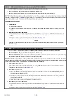
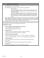
NO POWER-CHECK POWER CORD
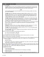
• ACTIVATION: The unit is set to operate in electric AND no AC power; incoming voltage at the High Volt-
age Transformer (HVT) is less than 300VAC.
• UNIT CONTROL: Engine Operation: System will remain in Engine Operation.
Electric Operation:
If the “NO A/C POWER” Configuration is set for “Alarm and shutdown” the refriger-
ation system will shutdown (because of the loss of power) with the alarm on and
PSCON still energized.
If the “NO A/C POWER” Configuration is set to “Switch To Diesel” the unit will
remain off for 5 minutes, then start the engine. The unit will remain in Engine Oper-
ation until the minimum run time has expired (regardless if the unit is set for Start
Stop or Continuous) and until electric power has been restored continually for 5
minutes.
• RESET CONDITION: Auto Reset when AC power is restored (HVT shows above 340VAC) or the alarm
may be manually reset via keypad or by turning the unit off, then back on. If the unit is running in Engine
Backup when the A/C power has been restored for 5 continuous minutes and the above conditions have
been met, the engine will stop and the unit will restart in Electric Operation.
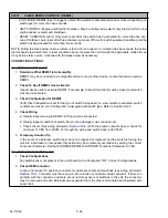
NOTE: Follow the steps below until a problem is found. Once a repair or correction has been made, the active
alarm should clear itself (see reset condition above). Operate the unit through the appropriate modes to see if
any active alarm occurs. Continue with the steps below as necessary.
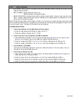
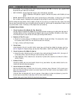
CORRECTIVE ACTIONS:
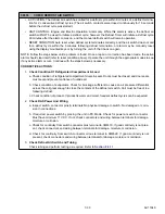
1.
Check Circuit Breaker On The Main External Power Supply
a. Check that the 30A supply circuit breaker is on.
b. Check the voltage in the plug. 460V / 3 / 60Hz.
2.
Check Power Cord
a. Inspect connections in the socket and the plug. Connections must be tight.
b. Inspect the cable. Cable must not be frayed, cut or damaged.
3.
Check For Power In The Control Box
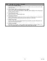
a. Check for voltage at PSCON L1-L2, L2-L3, L1-L3. All three readings must be 460V + 10%.
b. Check for voltage at PSCON2 L1-L2, L2-L3, L1-L3. All three readings must be 460V + 10%.
4.
Check Connections
Check for bad connections in the control box. Connections and wire crimps must be tight.
5.
Check CCB1
Check for voltage between 1CCB35 & 1CCB19. Voltage should be 0.766 V + 10%.
6.
Check CCON
Check for continuity between L1 or L2 to HVT. Check for open or shorted.
Содержание Vector 8500
Страница 23: ...62 11640 1 6 1 3 SAFETY DECALS ...
Страница 24: ...1 7 62 11640 62 03958 ...
Страница 25: ...62 11640 1 8 ...
Страница 26: ...1 9 62 11640 ...
Страница 27: ...62 11640 1 10 ...
Страница 125: ...62 11640 SECTION 6 MESSAGECENTER PARAGRAPH NUMBER Page 6 1 MESSAGECENTER MESSAGES 6 1 ...
Страница 321: ......
Страница 322: ......


