5–23
62-11640
PM 1
−
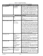
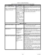
5 RESET INTERVAL
NOTE: This Configuration will not
display for those meters that are
configured for zero hours.
ENGINE HOURS 0 or
50 TO 30,000 hours in
50 hour increments
SWITCH ONHOURS 0
or 50 TO 30,000 hours
in 50 hour increments
STANDBY RUN
HOURS 0 or 50 TO
30,000 hours in 50 hour
increments
START CYCLES 0 or
1,000 TO 90,000 CY-
CLES in 1,000 cycle in-
crements
HIGH SPEED HOURS
0 or 50 TO 30,000
hours in 50 hour incre-
ments
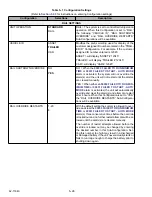
The value to be entered here is the desired number
of hours or cycles between PM Maintenance Alarms
for this meter.
When the meter is reset, the value selected here will
be added to the to the present meter reading to indi-
cate to the main microprocessor when the next ser-
vice interval alarm is to be activated.
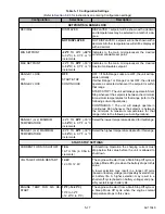
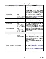
REMOTE SENSORS
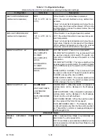
REMOTE TEMP SENSOR 1, 2 or
3
ON /
OFF
ON = A remote sensor has been added to the unit,
and connected into the wire harness.
OFF = There is no Remote Sensor (1, 2 or 3) in this
unit.
DOOR SWITCH
NOT INSTALLED
OPEN SWITCH
OPEN
OPEN SWITCH
CLOSED
NOT INSTALLED = There is no door switch.
OPEN SWITCH CLOSED = A Door switch has been
installed. The switch contacts will be CLOSED when-
ever the door is OPEN.
OPEN SWITCH OPEN = A Door switch has been in-
stalled. The switch contacts will be OPEN whenever
the door is OPEN.
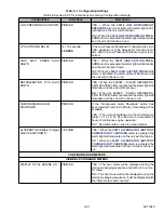
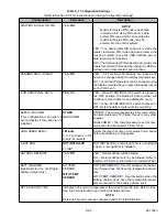
DOOR SWITCH SHUTDOWN
ALARM ONLY
UNIT SHUTDOWN
LOW ENGINE
SPEED
DATA RECORDER
ONLY
ALARM ONLY = When Door switch indicates that the
door is open, a warning alarm will be displayed in the
MessageCenter.
UNIT SHUTDOWN = When Door switch indicates
that the door is open, a warning alarm will be dis-
played in the MessageCenter, and the unit will shut-
down. If this setting is chosen the following sub-
setting will also be available.
LOW ENGINE SPEED = When Door switch indicates
that the door is open, the engine will be forced to low
speed. If this setting is chosen the following sub-set-
ting will also be available.
DATA RECORDER ONLY = The DataLink data re-
corder will record every time the door is opened or
closed. There will be no alarms or messages dis-
played in the MessageCenter.
Table 5–1 Configuration Settings
(Refer to
Section 5.2.3
for instructions on entering Configuration settings)
Configuration
Selections
Description
Содержание Vector 8500
Страница 23: ...62 11640 1 6 1 3 SAFETY DECALS ...
Страница 24: ...1 7 62 11640 62 03958 ...
Страница 25: ...62 11640 1 8 ...
Страница 26: ...1 9 62 11640 ...
Страница 27: ...62 11640 1 10 ...
Страница 125: ...62 11640 SECTION 6 MESSAGECENTER PARAGRAPH NUMBER Page 6 1 MESSAGECENTER MESSAGES 6 1 ...
Страница 321: ......
Страница 322: ......


