62-11640
8–16
6. If gauge reading is not close to the calculated
saturation pressure in step 5, noncondensibles
or mixed refrigerants are present.
7. Remove refrigerant. Refer to following step c.
8. Leak check, evacuate & recharge the system.
c. Removing Charge
1. If the system is in operating condition, it will be
quicker to remove the charge by continuing with
step 2. If the system is not in operating condi-
tion, skip steps 2 through 5 and continue with
step 6.
2. Install a manifold gauge set to allow reading of
suction and discharge pressure.
WARNING
!
Only a refrigerant cylinder that has previ-
ously been used with R404A should be
connected to this refrigeration unit.
3. Connect a clean, evacuated refrigerant cylinder
to the liquid line service valve connection. Place
the cylinder on a weight scale so the refrigerant
going into the cylinder can be monitored.
4. Start the unit and run in high speed cool. Cover
the condenser to raise the discharge pressure to
as high as 375 psig (25.5 bar). Do not let the
discharge pressure exceed 400 psig (27.2 bar).
Open the refrigerant cylinder valve, and allow
the refrigerant to flow into the cylinder. The
amount of refrigerant going into the cylinder can
be monitored by watching the weight of the cyl-
inder.
5. Shutdown the unit when the suction pressure
drops to 2 psig (0.2 bar). There should be very
little refrigerant remaining in the system at this
point.
6. Place the unit in Service Mode (Refer to
). Ensure that the operator message
panel displays “RECOVER/LEAK CHK/EVAC
MODE” during the refrigerant removal proce-
dures. If the control system switches to charge
mode during the process, switch it back to the
“RECOVER/LEAK CHK/EVAC MODE”.
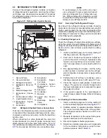
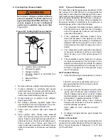
7. Connect a refrigerant recovery device and a
clean refrigerant recovery cylinder (or continue
to use the same cylinder used in step 3) as
shown in
ing refrigerant from the system.
8. Refer to instructions provided by the manufac-
turer of the refrigerant recovery unit.
9. After making necessary repairs, leak check,
evacuate and recharge the system.
d. Pumping Down The Low Side
Components on the low side of the refrigeration system
(the filter drier, EVXV, ECXV, evaporator coil, CSMV,
heat exchanger, suction line etc.) may be serviced or
replaced without having to completely remove the refrig-
erant charge from the system by pumping down the low
side, and temporarily storing the refrigerant in the con-
denser and receiver.
NOTICE
NOTICE The scroll compressor achieves
low suction pressure very quickly. Do not
use the compressor to evacuate the sys-
tem below 0 psig. Never operate the com-
pressor with the suction or discharge
service valves closed (frontseated). Inter-
nal damage will result from operating the
compressor in a deep vacuum.
1. Install a manifold gauge set to allow reading of
suction and discharge pressure.
2. Start the unit.
3. Frontseat the liquid line service valve.
4. Shutdown the unit when the suction pressure
drops to 2 psig (0.2 bar). There should be very
little refrigerant remaining in the low side of the
system at this point.
5. Monitor the gauges. The suction pressure
should not rise rapidly. If the suction pressure
continues to rise, the liquid line service valve
may not be properly closed. In this case, the low
side cannot be pumped down and the entire
refrigerant charge must be removed from the
system. (Refer to preceding step c.).
6. Ensure the unit will not start automatically by
disabling any two way communication and plac-
ing the STOP/RUN-OFF switch in the OFF posi-
tion. Disconnect the high voltage source and
lockout/tagout the receptacle.
7. Frontseat (close by turning clockwise) the dis-
charge service valve and the refrigerant will be
trapped between the compressor discharge ser-
vice valve and the liquid line service valve.
8. Before opening up any part of the low side of the
system, a slight positive pressure should be
indicated on the pressure gauge. If the pressure
is below 0 psig/ bar slowly open the liquid line
service valve slightly and then frontseat the
valve again. Repeat as necessary in order to
raise the pressure above zero.
9. Connect a refrigerant recovery device and a
clean refrigerant recovery cylinder to the suction
and discharge service valves and remove any
remaining refrigerant from the low side. DO
NOT bring the low side pressure below 0 psig/
bar.
Содержание Vector 8500
Страница 23: ...62 11640 1 6 1 3 SAFETY DECALS ...
Страница 24: ...1 7 62 11640 62 03958 ...
Страница 25: ...62 11640 1 8 ...
Страница 26: ...1 9 62 11640 ...
Страница 27: ...62 11640 1 10 ...
Страница 125: ...62 11640 SECTION 6 MESSAGECENTER PARAGRAPH NUMBER Page 6 1 MESSAGECENTER MESSAGES 6 1 ...
Страница 321: ......
Страница 322: ......


