62-11640
2–12
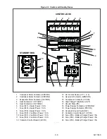
i. Overload Ground Fault Module (OGF)
Figure 2.7 OGF Module
The OGF, see
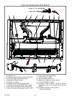
, is located in the control box
(
). The module has two electrical safety fea-
tures which are active in both Engine and Electric
Operation:
1. Overload protection.
2. Ground Fault (Leakage).
In each case, the 00100
−
“OVERLOAD/GROUND
FAULT” alarm is activated and the unit shuts down.
When ground leakage is detected, the red LED on the
OGF module will be on continuously.
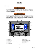
j. Display Module (DM)
LCD Display
The control system will display the refrigerated com-
partment temperature on the left and compartment set-
point on the right. The control system may be
configured to display the setpoint in either whole num-
bers or with tenths of a degree. The temperature
description will be followed by a letter indicating the
information is in degrees Fahrenheit (F) or degrees
Centigrade (C).
Message Center
Messages generated by the control system are dis-
played in the MessageCenter. Details of the messages
are described in
.
START/RUN-OFF Switch (SROS)
To stop the unit, place the SROS in the OFF position.
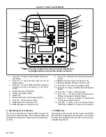
k. Display Module Keys
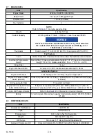
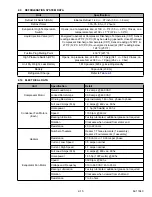
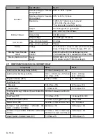
2.6
OPTIONS
2.6.1
Light Bar
The Light Bar is an external indicator light which can be
seen in the driver’s rear view mirror from the cab of the
tractor. The green LED indicates “STATUS OK”. The
amber LED indicates “CHECK UNIT”. The amber light
is illuminated when the control system illuminates the
alarm light. Alarms can be read on the display.
For units with EES installed, the amber light will also be
illuminated when the EES System is in Service Mode.
This does not affect unit operation.
When placed in the START/
RUN position, this switch pro-
vides power to start the unit.
The main microprocessor per-
forms a self-test. Then set-
point and compartment
temperatures are displayed.
LED
OFF
START/RUN
O
I
ALARM Key
The ALARM key allows viewing of the
alarms stored in the system.
UP ARROW and DOWN ARROW
Keys
These keys allow scrolling through the
selections presented.
EQUAL Key (ENTER)
The EQUAL key is used to confirm a
selection and lock it into the memory.
START-STOP/CONTINUOUS Key
Pressing this key toggles between
Start-Stop and Continuous Operation.
DEFROST Key
The MANUAL DEFROST key may be
used to initiate a defrost cycle when
the required conditions are met.
MENU Key
Pressing the MENU key displays the
various soft keys in the MessageCen-
ter. The selections offered are depen-
dent on the operator’s status: Driver,
Advanced User or Technician. Refer
to
for Driver & Advance
User mode and
for Techni-
cian mode menu selection descrip-
tions.
USB Interface Port
The USB Interface Port is used for
installing software updates, options,
configurations, functional parameters
and downloading of data from the
Data Link data recorder.
ALARM
START
‐
STOP
DEFROST
START
‐
STOP
CONTINUOUS
START/STOP
DEFROST
DEFROST
START
‐
STOP
MENU
Содержание Vector 8500
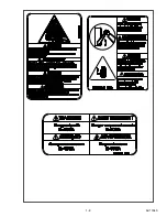
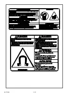
Страница 23: ...62 11640 1 6 1 3 SAFETY DECALS ...
Страница 24: ...1 7 62 11640 62 03958 ...
Страница 25: ...62 11640 1 8 ...
Страница 26: ...1 9 62 11640 ...
Страница 27: ...62 11640 1 10 ...
Страница 125: ...62 11640 SECTION 6 MESSAGECENTER PARAGRAPH NUMBER Page 6 1 MESSAGECENTER MESSAGES 6 1 ...
Страница 321: ......
Страница 322: ......

