background image

Error Correction 

DPM IV 


104 

Operating Manual 

05.18 


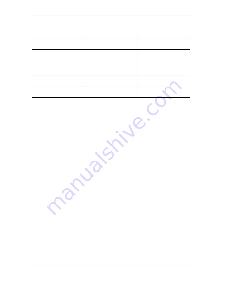
Error message 

Cause 

Remedy 

135  Script user error 

Error in LUA script user input. 

Correct the input value. 

136  No reprint available 

No label data for reprinting 
available. 

Send new label data to the 
printer. 

137  Printhead short 

circuit 

Electrical short at the printhead.  Check the used printhead. 

Please contact your distributor. 

138  Too little ribbon 

Transfer ribbon ends. 

Change transfer ribbon. 

139  Hardware error 

A hardware component could 
not be found. 

Please contact your 
responsible distributor. 


Содержание DPM IV

Страница 1: ......

Страница 2: ...ancies between manual and device can occur Please check www carl valentin de for the latest update Trademarks All named brands or trademarks are registered brands or registered trademarks of their respective owners and may not be separately labelled It must not be concluded from the missing labelling that it is not a registered brand or a registered trademark Carl Valentin print modules comply wit...

Страница 3: ...ustomized Counter Pressure Plate 32 5 6 Connection of Pneumatic Power Supply 33 5 7 Installing the Control Unit 34 5 8 Adjustment of Pressure Power 35 5 9 Connecting the Direct Print Module 36 5 10 Before Initial Operation 36 5 11 Print Control 37 5 12 Initiation 37 5 13 Loading Transfer Ribbon 38 5 14 Zero Point Adjustment 40 6 Function Menu 41 6 1 Print Settings 41 6 2 Machine Parameters 42 6 3 ...

Страница 4: ...ay 63 7 1 Touch Screen Display Structure 63 7 2 Different Menus 64 7 3 User Defined Info Field 65 7 4 Favorites List 67 7 5 Parameter Input 69 7 6 Navigation Zones 71 7 7 Maintenance Zone 72 7 8 Process Data 77 7 9 Memory Menu 79 7 10 Information Zone 81 7 11 Change to Foil Keyboard 81 8 Maintenance and Cleaning 83 8 1 General Cleaning 83 8 2 Cleaning the Transfer Ribbon Roller 84 8 3 Cleaning the...

Страница 5: ...machine equipment are avoided WARNING of hot surfaces Pay attention so as not to come into contact with hot surfaces CAUTION indicates a potentially dangerous situation which could lead to moderate or light bodily injury or damage to property NOTICE gives you tips They make a working sequence easier or draw attention to important working processes Gives you tips on protecting the environment Handl...

Страница 6: ...he socket is to be examined by a qualified technician Couple the direct print module to devices using extra low voltage only Before making or undoing connections switch off all devices involved computer printer accessories etc Operate the direct print module in a dry environment only and do not get it wet sprayed water mist etc Do not operate the direct print module in explosive atmosphere and not...

Страница 7: ...s then you and others cannot be aware of dangers and may be injured DANGER Danger to life and limb from power supply Do not open the casing CAUTION Two pole fuse Before opening the housing cover disconnect the device from the mains supply and wait for a moment until the power supply unit has discharged 1 4 Decommissioning and Dismantling NOTICE The decommissioning of printing system can only be ca...

Страница 8: ... be returned to Carl Valentin GmbH This way you can be sure your old equipment will be disposed of correctly Carl Valentin GmbH thereby fulfils all obligations regarding timely disposal of old equipment and facilitates the smooth reselling of these products Please understand that we can only take back equipment that is sent free of carriage charges The electronics board of the printing system is e...

Страница 9: ...fortable The device settings can be made by the integrated intuitive touch screen display By using most modern printhead technology we ensure a high standard of print quality Zeitsparendes Aktualisieren der Software ist über die Schnittstelle möglich Das Direktdruckwerk ist standardmäßig mit einer seriellen USB und Ethernet Schnittstelle ausgestattet Zusätzlich verfügt das Direktdruckwerk über ein...

Страница 10: ...ction I Connecting cable connection print mechanics control unit J Grounding bolt K Ribbon rewinder L Cover sensor M Zero adjustment N Zero control O Cable outlet at side P Cable outlet to top NOTICE No print job can be initiated when the covering hood is removed An internal cover sensor L examines the status of the cover open closed This sensor does not meet the requirements of a standard complia...

Страница 11: ...necting cable connection print mechanics control unit F USB port G Ethernet interface H USB host for USB keyboard and USB stick I External inputs outputs J Serial interface RS 232 K Mains connection L Grounding bolt M Power switch 1 LED green 1 Lighting Speed 100 MBit 1 Off Speed 10 MBit 2 LED orange 2 Lighting Connection avtive 2 Flashing Data transfer 2 Off No connection ...

Страница 12: ...er the printhead moves against the print medium Afterwards the printing carriage moves corresponding to the set or transferred layout length linear over the material which is to be printed After the print procedure the printhead again lifts up and the printing carriage moves again to the starting position ...

Страница 13: ...out regular training courses The content of the training are chapter Operating Conditions Loading Transfer Ribbon and General Cleaning These indications are also valid for someone else s equipment supplied by us Only use original spare and exchange parts Please contact the manufacturer with respect to spare wear parts The installation place of direct print module should be even free of vibration a...

Страница 14: ...chine can cause interferences in residential areas in this case it can be required from operator to accomplish appropriate measures and be responsible for it All connecting lines have to be guided in shielded lines Shielding has to be connected on both sides to the corner shell It is not allowed to guide lines parallel to power lines If a parallel guiding cannot be avoided a distance of at least 0...

Страница 15: ...on of environment Building alterations of our direct print modules Incorrect programming and operation Not performed data protection Using of not original spare parts and accessories Natural wear and tear When re installing or programming our direct print modules please control the new settings by test running and test printing Herewith you avoid faulty results reports and evaluation Only speciall...

Страница 16: ...he notes to the direct print module maintenance in order to avoid damages or premature wear We endeavoured to write this manual in an understandable form to give and you as much as possible information If you have any queries or if you discover errors please inform us to give us the possibility to correct and improve our manual ...

Страница 17: ...ics approx 9 16 kg depending on print length print width Control unit approx 5 5 kg without connection lines Connection cable approx 0 85 kg print mechanics control unit Electronics Processor High Speed 32 Bit RAM 16 MB Slot Compact Flash card type I Battery cache for Real Time clock storage of data with shut down Warning signal acoustic signal when error Interfaces Serial RS 232C up to 115 200 Ba...

Страница 18: ...2 9 orientation 0 90 180 270 Vektor fonts TrueType fonts size in width and height 1 99 mm variable zoom orientation 0 90 180 270 Font attributes depending on character font bold Italic inverse vertical Font width variable Bar codes 1D bar codes CODABAR Code 128 Code 2 5 interleaved Code 39 Code 39 extended Code 93 EAN 13 EAN 8 EAN ADD ON GS1 128 Identcode ITF 14 Leitcode Pharmacode PZN 7 Code PZN ...

Страница 19: ...The ports are provided by means of a D Sub bushing 26pin HD at the rear panel of the printer system and are galvanically isolated from protective earth PE by means of an optocoupler semi conductor route Each port can be configured as input and as output This function however is predefined in the printer software and cannot be changed by the user The following parameters can be changed and set by u...

Страница 20: ...erminal of the control voltage and the control inputs are switched to active By means of the option 2nd LED COM VDC for Inputs can optionally be connected with the terminal of the control voltage Then the control inputs are switched to active VDC for Outputs 20 Common supply connection of all control outputs VDC for Outputs must be connected with the terminal of the control voltage Never leave VDC...

Страница 21: ... can be used e g as control voltage Never apply any external voltage to this output Port 1 to Port 16 Assignment for I O Profile Std_Direct Port Pin Description Function 11 Input 10 Print start 12 Input 11 No function 13 Input 11 Counter reset 14 Input 12 No function 15 Input 12 Error reset 16 Input 13 No function 17 Input 13 No function 18 Input 14 No function 19 Output 15 Error 10 Output 16 No f...

Страница 22: ...ad Bit 5 Input 19 Output 15 Error 10 Output 16 No function 11 Output 16 No function 12 Output 17 No function 13 Output 17 Ready 14 Output 18 No function 15 Output 18 Return printing carriage 16 Output 19 Transfer ribbon prior warning The files must be saved onto the CF card in the user directory The files must start with 1 or 2 digits 1_Etikett prn 02_Etikett prn The files can be saved with a file...

Страница 23: ...t 17 Printing 13 Output 17 Ready 14 Output 18 No function 15 Output 18 Return 16 Output 19 Transfer ribbon prior warning Port 1 to Port 16 Assignment for I O Profile Old_Direct0 Port Pin Description Function 11 Input 10 Print start 12 Input 11 Error reset 13 Input 11 Counter reset 14 Input 12 No function 15 Input 12 No function 16 Input 13 No function 17 Input 13 No function 18 Input 14 No functio...

Страница 24: ...100nF 10 kΩ Output Tension 5 VDC 24 VDC Impedance 47Ω 100nF 10 kΩ 47Ω Current max High 15 mA Low 15 mA Port 16 Input Tension 5 VDC 24 VDC Impedance 100nF 10 kΩ Output Tension 5 VDC 24 VDC Impedance 100nF 10 kΩ Current max High 500 mA Darlington BCP56 16 Low 500 mA Darlington BCP56 16 Optocoupler Output TCMT4106 CTR 100 300 Vishay or TLP281 4 GB CTR 100 600 Toshiba Input TCMT4106 CTR 100 300 Vishay...

Страница 25: ...DPM IV Technical Data 05 18 Operating Manual 25 Device connection to a machine with S7 300 SPS Figure 6 Device connection to a operating panel Figure 7 Example 1 Example 2 ...

Страница 26: ...nternal voltages 5 VDC EXT or 24 VDC EXT is used an external fuse e g 0 5 AF should be additionally installed to protect the printer electronics In the event of an inductive load an antiparallel connected diode for instance must be used to discharge the induction energy In order to minimize the influence of leakage currents at control outputs a resistor must depending on what is connected be insta...

Страница 27: ...ng system against uncontrolled movement Check the direct print module for transport damages Remove foam transportation safeguards near the printhead Check delivery for completeness Print mechanics Control unit with cable Connecting cable Mini controller Manometer Pneumatic tube Push on connector I O accessories mating connector for I O 1 transfer ribbon roll Empty core mounted on transfer ribbon r...

Страница 28: ...o this instruction At the side parts of print mechanics C are two M6 threads D on the upper and back side which can be used for the attachment of print mechanics to a machine The maximum thread depth is 12 mm The connecting cable A to control unit can be led from the printing system to top or to the side The pneumatic tube Ø 8 mm B can be led from the printing system alternatively to top or to the...

Страница 29: ...n 05 18 Operating Manual 29 5 2 Installation Position Without Brake NOTICE For integration of the print mechanics into a packaging machine the following outlined installation positions without the optional brake are approved Figure 10 ...

Страница 30: ...owever this must be examined in individual cases Vibrations at the packaging machine can require a brake CAUTION Danger of injury and malfunctions by uncontrolled movements of the printing carriage Retrofit brake Otherwise unexpected linear movement of the printing carriage can result see the outlined installation positions Particularly with zero position at top and in de energised state e g power...

Страница 31: ...aded holes are designated at the bottom of the print mechanics D The suitable screws B are included with delivery of this option The suitable distance between printhead and counter pressure plate is already preset see Figure 13 On the bottom face of the carrier of counter pressure plate A are threaded holes M4 C which can be used for mounting the unit onto a plate or similar A C B D Figure 12 ...

Страница 32: ...entations in the counter pressure plate of just 1 100 mm can cause a worse print quality at these points The counter pressure plate must be placed in such a way to get a distance of 1 2 5 mm see illustration between the printhead A and the upper side of the counter pressure plate B NOTICE A distance of 2 mm is recommended For the protection of printhead A related to the print length the counter pr...

Страница 33: ...n pressure regulator and print mechanics is established by a pneumatic tube Ø 8 mm and an appropriate push in fitting The following points should be observed Place the pressure regulator as near as possible to the print mechanics The pressure regulator is only to operate in the direction of the arrow see label at pressure regulator The direction shows the way of the streaming air In no case bend p...

Страница 34: ... for the attachment of control unit at a machine The maximum thread depth is 8 mm Ex works optionally a mounting bracket E is offered which can be used to the pivoting support of control unit A to the threaded holes B The mounting bracket can be fastened standing or hanging with four screws M6 D at a machine Ex works optionally a fixing flange Ø 30 mm or a base clamp Ø 30 mm are offered which can ...

Страница 35: ...n be set with the pressure regulator The values are indicated in the following table NOTICE If the pressure power is set too low then the printhead has no more contact to the counter pressure plate This damages the printhead due to the missing heat dissipation during the printout In case of too low pressure an error message appears This error message is to protect the printhead for overheating onl...

Страница 36: ...outlet NOTICE Insufficient or missing grounding can cause faults during operation Ensure that all computers and connection cables connected to the direct print module are grounded Connect direct print module to computer or network with a suitable cable 5 10 Before Initial Operation 1 Mount print mechanics 2 Connect all cables between print mechanics and control unit and protect cables against unin...

Страница 37: ...nterfaces serial USB or Ethernet The print is started by a start signal to the print start control input It is necessary for the control unit to recognise the moment of setting the start signal and therefore it is possible and also necessary to observe the print status by the outputs 5 12 Initiation Once all connections have been made Switch control unit on with the power switch Insert transfer ri...

Страница 38: ...printhead with printhead and roll cleaner 97 20 002 For detailed information please see page 84 The handling instructions for the use of Isopropanol IPA must be observed In the case of skin or eye contact immediately wash off the fluid thoroughly with running water If the irritation persists consult a doctor Ensure good ventilation 1 Open the cover of print mechanics CAUTION Risk of scraping when ...

Страница 39: ... tape to the empty roll and tighten the transfer ribbon with some turns of the roll 6 Close the cover of print mechanics CAUTION Risk of crushing and damage to objects when closing the dust cover When closing the dust cover ensure that neither parts of the body nor objects e g clothes jewelery are clamped CAUTION Impact of static material on people Use antistatic transfer ribbon because static dis...

Страница 40: ...rinting carriage A with the slider B 2 If the slider is at shaft end side panel the maximum print length is available 3 By adjusting the printer zero point the usable print area is shortened 4 Use the zero point adjustment for adjusting the print position onto the foil 5 The zero point monitoring is made by an inductive proximity switch C ...

Страница 41: ...ibbon was torn at the unwinding roll Off The ribbon control is deselected i e the printer continues without an error message On The ribbon control is selected i e the current print order is interrupted and an Error Message appears at the printer display Strong sensibility The printer reacts immediately to the end of the transfer ribbon Weak sensibility The printer reacts at approx 1 3 more slowly ...

Страница 42: ...it is terminated by the user or in case of new data transmission Test mode This operating mode corresponds to mode 2 After the return of the print unit to the zero point of the machine however internally a further cycle is started endurance test Direct start A print order is transferred After termination of generating process the print order is executed without an external signal Indication of bac...

Страница 43: ... must be available and set to On If the printing system is mounted in horizontal or in varying position the optional brake if available is set to Off in order to avoid a decelerating during printing Indication of delay in 1 100 seconds The closing of brake can be delayed If during the delay time no start impulse for printing a new cycle is effected then the brake is closed If the delay time is set...

Страница 44: ...rinthead is used It is recommended to use layouts with the same width as the printhead Otherwise this can cause problems in positioning According to standard the layout is printed ahead with a rotation of 0 If the function is activated the layout is rotated by 180 and printed in reading direction The adjustment of layout is effected only after Flip Rotate layout i e the adjustment is independent o...

Страница 45: ... are to be made directly at the printing system On Sending parameters such as speed and contrast via our design software to the printing system Parameters which are set directly at the printing system before are no longer considered Off Only settings made directly at the printing system are considered On The question referring the customized variable appears once before the print start at the disp...

Страница 46: ...print module The following possibilities are available Codepage 1252 West European former ANSI Codepage 437 English Codepage 850 Western European Codepage 852 Slavic Codepage 857 Turkish Codepage 1250 Central and East European Codepage 1251 Cyrillic Codepage 1253 Greek Codepage 1254 Turkish Codepage 1257 Baltic WGL4 Please find the tables referring to the above mentioned character sets on www carl...

Страница 47: ... is started without previous definition of layout an error message appears in the display 6 4 3 User Environment On An acoustic signal is audible when pressing a key Off No signal is audible 6 4 4 General Parameters Selection of language the display indicates texts in the graphic display At the moment the following languages are available German English French Spanish Dutch Italian Czech Hungarian...

Страница 48: ...or warning 6 5 3 General Parameters Selection of existing configurations Std_Direct factory setting StdFileSelDirect SP_Direct0 or Old_Direct0 The corresponding assignment is indicated in chapter 4 1 page 19 Indication of debounce time of the dispenser input The setting range of the debounce time is between 0 and 100 ms In case the start signal is not clear then you can debounce the input by means...

Страница 49: ...time can be saved and performance be increased Off The start signal for the next layout can only be released if the current layout is printed to the end and the printing system is again in waiting state output ready set If the start signal was released already before so this is ignored On If a print order is active but the direct print module is not ready to process the order e g if it is already ...

Страница 50: ...ement This value is added to the acceleration time of transfer ribbon movement Time indication for the time between motor reached material speed and printhead burns If the same value is entered as for PhDownT the printhead upwards movement is not started before the transfer ribbon motor reached the material speed It is calculated when the printhead upwards movement is started Off Field ribbon savi...

Страница 51: ... transmission method 100 Mbit half Speed 100 MBit s in the half duplex transmission method 100 Mbit full Speed 100 MBit s in the full duplex transmission method DHCP permits the automatic referring of the network parameters IP address network mask and standard gateway of a DHCP server which must be installed in the network The name of the installed printer in the network The printer name in connec...

Страница 52: ...range 1 or 2 stop bits 6 8 2 General Parameters SOH Start of data transfer block Hex format 01 ETB End of data transfer block Hex formal 17 Two different start en signs can be set The settings are normally SOH 01 HEX and ETB 17 HEX Several host computers cannot process these signs and therefore SOH 5E HEX and ETB 5F cannot be set Off After starting a print order no more data is received Standard A...

Страница 53: ... that of the Valentin printer then the size of objects e g texts graphics complies not exactly The access to drives B CF cart E Flash drive R RAM disk standard drive if not indicated is rerouted to the corresponding Valentin drives A CF R RAM disk U USB stick This can be necessary if the available space on the RAM disk at present 512 KByte is not sufficient or if bitmap fonts are downloaded to the...

Страница 54: ...nth when the daylight saving time should begin Selection of time when the daylight saving time should begin 6 10 3 End Daylight Saving Time Selection of format to enter the end of the daylight saving time The example shows the standard settings European format Selection of the week when the daylight saving time should end Selection of the weekday when the daylight saving time should end Selection ...

Страница 55: ...le attainment in meters To achieve a high print quality the indicated Ohm value must be set after an exchange of printhead Indication of printhead temperature The printhead temperature corresponds normally to the room temperature In case the maximum printhead temperature is exceeded the current print order is interrupted and an error message appears at the direct print module display This function...

Страница 56: ...d print speed in mm s This can be set in the limits of the normal print speed Roll diameter Indication how much transfer ribbon is still on the transfer ribbon roll For a correct display some layouts must be reprinted Time left Indication during a current print order how long it can be printed with the existing transfer ribbon 6 11 4 I O Status The start input impulses are counted directly at the ...

Страница 57: ...nt start 2 Reset error 3 Counter reset 4 No function 5 No function 6 No function 7 No function 8 No function Indication of output signal level 0 Low 1 High Port Function 9 Error 10 Print order active 11 Generating 12 Print end 13 Ready 14 Error 15 Return 16 Ribbon prior warning I O status input I O status output ...

Страница 58: ...e number for developers LogMemStd txt Logging of selected events LogMemNet txt Data latest send via port 9100 Parameters log All printer parameters in human readable form TaskStatus txt Status of all printer tasks The files LogMemErr txt and LogMemStd txt are written in circle i e old contents are overwritten The entry logged last is marked with 6 12 Password With a password different functions ca...

Страница 59: ... the password protection prevents that prints can be produced manually In order to execute a blocked function first of all the valid password has to be entered If the correct password is entered then the desired function can be executed 6 12 2 Network Entering a 15 digit password The password can consist of alphanumeric and special characters The communication by HTTP can be avoided The settings o...

Страница 60: ...anual zoom factor to scale the complete layout down The display of label preview can be rotated on the touch screen display On The label preview is shown rotated by 180 on the display Off The label preview is represented in read direction During a running print order the preview is refreshed in the set interval With activated print preview the currently printed layout is shown on the display Wipe ...

Страница 61: ...80 The display is represented turned by 180 degres 6 13 3 System Settings NOTICE All settings and modifications in system settings require the respective password The following system settings can be made Device type Reset paper counter printhead Reset paper counter device Set default settings OEM client ID 6 14 Main Menu Switch on the direct print module and the display shows the Home screen Pres...

Страница 62: ...Function Menu DPM IV 62 Operating Manual 05 18 ...

Страница 63: ...he print order alerts in case of an error and indicates the device settings in the menu The desired settings are made by selecting the buttons on the touch screen display Favorites Display favorites list Configuration Select parameter settings Memory Card Access to memory card menu Print Start print job Test print Start test print Formfeed Start layout feed Info List of the installed components Cu...

Страница 64: ...ckground If a selected menu contains so called submenus these are blue highlighted Different parameters are combined in a submenu The left display side shows the available submenus The currently selected active submenu is highlighted on orange background Press to return one level Indication of main menus Indication of submenus ...

Страница 65: ...7 3 User Defined Info Field From the predefined contents the user can define the display of the user defined info field green Select menu Maintenance System settings User defined info field to specify what is to be displayed in the user defined info field ...

Страница 66: ...on Indication of job info label name and number of printed labels Job info Indication of label names and the number of already printed IP configuration Indication of IP address and MAC address of printing system Printed labels Indication of printed labels as enlarged text output Selection of parameters Display of predefined configuration ...

Страница 67: ...05 18 Operating Manual 67 7 4 Favorites List Press long 2 s on a parameter e g print speed to display the appropriate selection Press Add to favorites to add the selected parameter to the favorites list Add parameters to favorites ...

Страница 68: ...V 68 Operating Manual 05 18 Press long 2 s on a parameter e g print speed to display the appropriate selection Press Remove from favorites to remove the selected parameter from the favorites list Remove parameters from favorites ...

Страница 69: ...nual 69 7 5 Parameter Input In the header of input dialog the name of the parameter and the permissible value range are shown The input is checked for validity If the entered value not permissible the button is blocked Parameter input Numeric input ...

Страница 70: ...er for which you want to change the selection The currently selected value is highlighted on orange background Press to confirm the selection The alphanumeric input is shown in the header of input dialog Press to confirm the selection Selection from list Alphanumeric input ...

Страница 71: ...n variant a certain pressure on the display is needed It is not possible to navigate on the display with the swipe movement to the left and right with a finger well known from smartphones The position indications signalise the detail of the total list currently visible If no position indication is visible then the total list can be displayed on the display A swipe movement from top to bottom and o...

Страница 72: ...Zone Different settings for the display indication can be done With activated print preview a picture of the currently printed layout is shown on the display If the function is not activated the field remains empty Maintenance Print preview Print preview activated On Off ...

Страница 73: ...e indication zone Fields Only the print range is fit to the indication zone 1 8 Manual zoom factor to scale the complete layout down The display of label preview can be rotated on the touch screen display On The label preview is shown rotated by 180 on the display Off The label preview is represented in read direction Print preview Zoom Print preview Preview rotated ...

Страница 74: ... Manual 05 18 During a running print order the preview is refreshed in the set interval Value range 0 10 seconds In the LCD maintenance sector different parameters ro the touch screeen display can be set Print preview Interval Maintenance LCD ...

Страница 75: ... Landscape 180 The display is represented turned by 180 degres to the function Landscape Landscape The display is represented turned by 90 degres to the reading direction Portrait The display is represented in reading direction Portrait 180 The display is represented turned by 180 degres LCD Backlight LCD Orientation ...

Страница 76: ...play DPM IV 76 Operating Manual 05 18 Different system settings such as set printer type reset paper counter etc can be made However for the settings the corresponding password is necessary Maintenance System settings ...

Страница 77: ...e parameter must be activated before in the menu Maintenance Print preview Press long 2 s on a parameter e g current time to display the appropriate selection Press Add to process data to add the selected parameter to the process data list Activation of display for process data Add parameter to process data ...

Страница 78: ...elected parameter from the process data list With activated print preview the display shows a picture of the currently printed layout The change to the process data view is effected by wiping to the right With activated print preview on the display a picture of the up to date printed layout is shown Remove parameter from process data Change of display vies Process data Print preview ...

Страница 79: ...ory is shown one below the other The preview zone in on the right side is If available the preview of the selected layout is shown Load The selected layout is loaded After the number of copies have been entered the print order is started Admininstrative tools Switching to the file manager File Explorer Compact Flash Card USB Stick ...

Страница 80: ...Screen Display DPM IV 80 Operating Manual 05 18 The user query can be entered at the cursor position Press to change to the input of number of copies Enter the number of layouts to be printed Number of copies ...

Страница 81: ...nce more the Home view is again displayed 7 11 Change to Foil Keyboard Press long 3 s on the company logo left above and the display changes to the indication of a conventionalize foil keyboard The settings can be done by the standard operating panel Press to change to the previous view For more information about the use of printer and its foil keyboard can be found in chapter 6 page 41 ...

Страница 82: ...Touch Screen Display DPM IV 82 Operating Manual 05 18 ...

Страница 83: ...d or when the printout is adversely affected Cleaning printhead see chapter 8 3 page 84 Each time the transfer ribbon is changed or when the printout is adversely affected Replacing printhead see chapter 8 4 page 86 In case of errors in printout NOTICE The handling instructions for the use of Isopropanol IPA must be observed In the case of skin or eye contact immediately wash off the fluid thoroug...

Страница 84: ...er Ribbon Roller A soiled print roll can lead to reduced print quality and can affect transport of material B A Figure 18 1 Open the cover of print mechanics 2 Remove transfer ribbon 3 Remove deposits with roller cleaner and a soft cloth 4 If the roller A appears damaged replace it ...

Страница 85: ...ds depending on operating hours environmental effects such as dust etc CAUTION Printhead can be damaged Do not use sharp or hard objects to clean the printhead Do not touch protective glass layer of the printhead B A Figure 19 1 Open the cover of print mechanics 2 Remove transfer ribbon 3 Clean printhead surface with special cleaning pen or a cotton swab dipped in pure alcohol 4 Allow printhead to...

Страница 86: ...ive surface Ground your body e g by wearing a grounded wristband Do not touch contacts on the plug connections Do not touch printing line 5 with hard objects or your hands A B A C C Figure 20 1 Open the cover of print mechanics 2 Remove transfer ribbon material 3 Move printhead unit in an appropriate service position 4 Remove printhead cable C 5 Remove screws A and afterwards the printhead B Remov...

Страница 87: ...crew again screws A and tighten it 4 Connect again printhead cable C 5 Insert again the transfer ribbon material see 5 13 on page 38 6 Enter the resistance value of the new printhead in the Service Functions heater resistance The value is indicated on the type plate of printhead 7 Start a test print to check printhead position Installing the printhead ...

Страница 88: ...ways overturn of the printhead CAUTION Folding at transfer ribbon Change factory settings only in exceptional cases 1 By loosen a nut the printhead moves down at the corresponding side The transfer ribbon tension is increased 2 By tightening a nut the printhead moves up at the corresponding side The transfer ribbon tension is reduced NOTICE A strong regulation has result to the pressure power of p...

Страница 89: ...ead by unequal use Higher wastage of ribbon by faster ripping Change factory settings only in exceptional cases 1 Loosen slightly two Allen head screws A 2 Move threaded screws C to adjust the angle between printhead and printhead support Tighten decrease angle Loosen increase angle 3 Both threaded screws C must be adjusted with the very same number of turns 4 Tighten again the Allen head screws A...

Страница 90: ...nt quality Increase contrast Increase pressure Reduce print speed Reduce transfer ribbon speed Reduce distance between printhead and print surface Change combination of transfer ribbon and print medium Control print surface hardness Change printhead angle Partial inferior print quality on one side Align surface parallel to printhead Set regular transfer ribbon tension Set regular printhead angle P...

Страница 91: ...the effective print speed and it this way the clock cycle Generally increase the print speed Generally increase the back speed Increase acceleration and brake ramp Change zero point of machine Avoid vertical installation position of print mechanics Install the machine in horizontal position Control the short distance between printhead and print surface Optimise the layout to a short print way i e ...

Страница 92: ...Maintenance and Cleaning DPM IV 92 Operating Manual 05 18 ...

Страница 93: ...DPM IV Signal Diagrams 05 18 Operating Manual 93 9 Signal Diagrams 9 1 Mode 1 Single Item Processing ...

Страница 94: ...Signal Diagrams DPM IV 94 Operating Manual 05 18 9 2 Mode 2 Continuous Mode ...

Страница 95: ...lable Check font 8 Measuring label While measuring no label was found Set label length is too large Check label length and if labels are inserted correctly Restart measuring anew 9 No label found No label available Soiled label photocell Labels not inserted correctly Insert new label roll Check if labels are inserted correctly Clean the label photocell 10 No ribbon During the print order the ribbo...

Страница 96: ...t anew Check code data 21 Invalid SC number Selected SC factor is invalid for EAN res UPC Check SC factor 22 Invalid number of digits Entered digits for EAN res UPC are invalid 12 13 Check number of digits 23 Check digit calculation Selected check digit calculation is not available in the bar code Check calculation of check digit Check bar code type 24 Invalid extension Selected zoom factor is not...

Страница 97: ...rinthead and start print order anew 36 BCD invalid format BCD error Invalid format for the calculation of Euro variable Check entered format 37 BCD overflow BCD error Invalid format for the calculation of Euro variable Check entered format 38 BCD division BCD error Invalid format for the calculation of Euro variable Check entered format 39 FLASH ERROR Flash component error Run a software update Ch...

Страница 98: ...required files 54 File directory exists The selected file directory already exists Check name select a different name 55 File too large During copying procedure not enough memory space onto target drive available Use a larger target card 56 No update file Errors in update file of firmware Start update file anew 57 Invalid graphic file The selected file does not contain graphic data Check file name...

Страница 99: ...h is to print Exchange printhead 71 Invalid page As page number either 0 or a number 9 is selected Select a number between 1 and 9 72 Page selection A page which is not available is selected Check the defined pages 73 Page not defined The page is not defined Check the print definition 74 Format user guiding Wrong format for customised entry Check the format string 75 Format date time Wrong format ...

Страница 100: ...Displace RFID unit or use an offset 88 RFID verify Error while checking programmed data Faulty RFID label Check RFID definitions 89 RFID timeout Error at programming the RFID label Label positioning Faulty label 90 RFID data Faulty or incomplete definition of RFID data Check RFID data definitions 91 RFID tag type Definition of label data does not correspond with the used label Check storage partit...

Страница 101: ...issing option APL 100 Check input signals compressed air supply 102 Vacuum plate empty Sensor does not recognise a label at vacuum plate option APL 100 Check input signals compressed air supply 103 Start signal Print order is active but device not ready to process it Check start signal 104 No print data Print data outside the defined label Selection of wrong module type design software Check selec...

Страница 102: ... for cross traverse 116 Print position The print position is not correct Check TOP and RIGHT final position switch for correct function and position Check pneumatics for function 117 XML parameter The parameters in the XML file are not correct Please contact your responsible distributor 118 Invalid variable Transferred variable is invalid with customized entry Select correct variable without custo...

Страница 103: ...ion RFID programming faulty Run RFID initialising 127 Module not found RFID module not available Check the RFID module connection Please contact your responsible distributor 128 No release signal No print release by higher level control customer machine Activate release signal at the higher level control 129 Wrong firmware Firmware does not match the used printer type Use firmware that fits to the...

Страница 104: ...available No label data for reprinting available Send new label data to the printer 137 Printhead short circuit Electrical short at the printhead Check the used printhead Please contact your distributor 138 Too little ribbon Transfer ribbon ends Change transfer ribbon 139 Hardware error A hardware component could not be found Please contact your responsible distributor ...

Страница 105: ...ponding directory of the CF card However the following conditions have to be fulfilled CF card inserted in drive A CF card not write protected Enough free storage space onto CF card An error message appears in case these conditions are not fulfilled At switching off the direct print module the state of the current print order is saved to the corresponding directory of the CF card However the follo...

Страница 106: ...omized entry was active during switching off the direct print module the window for the first customized variable is displayed As in the intended file only the start values of the counter are saved they are refreshed at a new start of the print order by means of the number of printed layouts Each counter is counted corresponding from its start value Afterwards the position of the current and the n...

Страница 107: ...ving timet 54 Start daylight saving time 54 Delivery scope 27 Device settings Print control 46 47 Print job 45 46 User environment 47 E Environmentally friendly disposal 8 Error messages Error corrections 95 96 97 98 99 100 101 102 103 104 F Figures Control unit 11 Print mechanics 10 Function menu Date time 54 Device settings 45 46 47 Emulation 53 I O parameter 48 49 Interface 52 Layout 44 Machine...

Страница 108: ...tion Without brake 29 Installation Position With brake 30 Instructions 5 Intended use 5 6 L Layout Layout settings 44 M Machine overview 9 Maintenance LCD 61 Print preview 60 System settings 61 Maintenance cleaning Angle adjustment 89 Cleaning printhead 85 Cycle optimisation 91 General cleaning 83 Print quality optimisation 90 Replacing printhead 86 87 Ribbon roller cleaning 84 Schedule 83 Transfe...

Страница 109: ... Service functions I O status 56 Signal diagram Mode 1 single item processing 93 Mode 2 continuous mode 94 T Technical data 17 18 Touch screen display Alphanumeric input 70 Favorites list 67 68 Foil keyboard display 81 Information zone 81 Main menus 64 Maintenance zone 72 73 74 75 76 Memory menu 79 80 Navigation zones 71 Numeric input 69 Parameter input 69 Process data 77 78 Structure 63 Submenus ...

Страница 110: ......

Отзывы: