docs.carbide3d.com
8/31/2020
Version 4.0
58
Install the Y-Axis Proximity Switch
HDZ Kit + Carryover Components:
Item
Description
Qty
DD
Y-Axis Proximity Switch (Installed in the Drag Chain)
[CARRYOVER]
1
W
Y-Axis Proximity Switch Mount
1
X
M5 × 35mm Socket Head Cap Screw
2
Y
M3 × 18mm Socket Head Cap Screw
2
1.
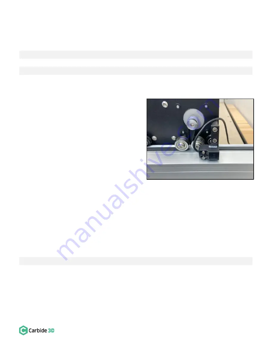
Install the Y-Axis proximity switch mount to the
outside of the Y2-carriage. See
Fig. 21
.
a.
Use a 4mm hex key and two (2) M5
×
35mm
SHCS to secure the mount to the outside of
the Y2-carriage.
2.
Attach Y-Axis proximity switch to the mount. See
Fig. 21
.
a.
Locate the Y-Axis proximity switch exiting
the drag chain at the Y1-Axis head bracket.
b.
Position the proximity switch with the red
LED facing out and the target pointing to
the rear.
c.
Align the switch
’s two mounting slots with
the two M3 PEM nuts on the mount.
d.
Use a 2.5mm hex key and two (2) M3
×
18mm SHCS to secure.
e.
Before fully tightening the screws, slide the switch as far to the FRONT as it will go.
Connect and Cleanup Wiring
HDZ Kit:
Item
Description
Qty
CC
Cable Ties
Several
1.
Connect the X- and Z-motor lead cables to their labeled extension cables at the rear of the HDZ.
a.
Both the X- and Z-motor extensions exit the head of the X-Axis drag chain behind the HDZ.
b.
Connectors are polarized. Be sure to align them properly.
2.
Use a couple of cable ties to tidy up the X- and Z-motor cables at the rear of the HDZ.
Figure 21
Содержание Shapeoko HDZ 4.0
Страница 1: ...support carbide3d com docs carbide3d com 9 2 2020 Version 4 0 1 ASSEMBLY GUIDE HDZ 4 0...
Страница 2: ...support carbide3d com docs carbide3d com 9 2 2020 Version 4 0 2...
Страница 8: ...support carbide3d com docs carbide3d com 8 31 2020 Version 4 0 8 Figure 2...
Страница 42: ...support carbide3d com docs carbide3d com 8 31 2020 Version 4 0 42 Figure 2...


