


Chapter 4
4-23
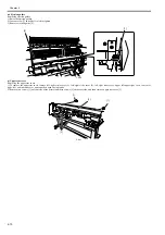
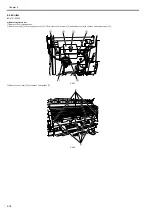
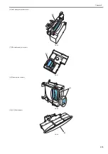
b) Precaution in mounting the carriage unit
Make sure that linear scale [1] is seated in linear encoder sensor [2].
F-4-49
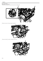
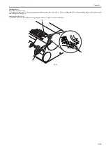
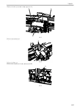
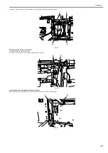
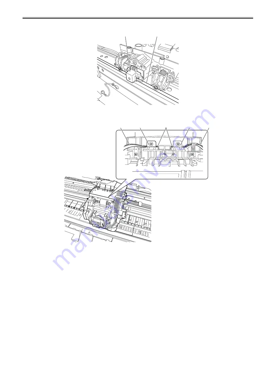
c) Mounting the carriage belt
To install the carriage belt, put in the point of the belt to the interior of the groove [1], and have all the cogs of carriage belt [3] engaged with belt stopper [2].
F-4-50
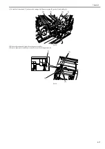
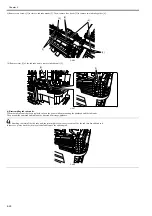
d) Note on replacing the carriage unit and the multi sensor
When either carriage unit or multi sensor has been replaced, be sure to replace the multi sensor reference plate(QL2-2840-000:MOUNT, MULTI SENSOR REF-
ERENCE) as well.
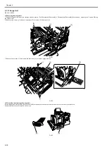
e) Action to take after replacing the carriage unit and the multi sensor
Because the distance between the multi sensor (in the carriage unit) and the nozzles (in each printhead) is varied from one unit to another, the printer has its optical
axis corrected and paper gap adjustment sensor gain and sensor calibration adjusted prior to shipment. When the carriage unit or multi sensor has been replaced,
they should require adjustment.
Execute service mode under the following conditions to launch automatic adjustment:
1) Optical axis correction
- Service mode: SERVICE MODE > ADJUST > PRINT PATTERN > OPTICAL AXIS
Media type: Gloss photo paper
2) Paper gap adjustment
- Service mode: SERVICE MODE > ADJUST > GAP CALIB.
[2]
[1]
[1]
[2]
[3]
[3]
[2]
Содержание iPF800 Series
Страница 1: ...Aug 13 2008 Service Manual iPF800 series ...
Страница 2: ......
Страница 6: ......
Страница 11: ...Chapter 1 PRODUCT DESCRIPTION ...
Страница 12: ......
Страница 14: ......
Страница 38: ...Chapter 1 1 24 Hold this lever to pull out the lower roll unit ...
Страница 90: ...Chapter 1 1 76 3 Push in the left and right Basket Rods toward the back all the way until they stop F 1 41 ...
Страница 100: ...Chapter 1 1 86 ...
Страница 101: ...Chapter 2 TECHNICAL REFERENCE ...
Страница 102: ......
Страница 147: ...Chapter 2 2 43 This function relays the image data from the main controller PCB to the printhead ...
Страница 158: ......
Страница 159: ...Chapter 3 INSTALLATION ...
Страница 160: ......
Страница 162: ......
Страница 176: ...Chapter 3 3 14 ...
Страница 177: ...Chapter 4 DISASSEMBLY REASSEMBLY ...
Страница 178: ......
Страница 180: ......
Страница 227: ...Chapter 4 4 47 Media type Gloss photo paper 2 Paper gap adjustment Service mode SERVICE MODE ADJUST GAP CALIB ...
Страница 238: ...Chapter 4 4 58 ...
Страница 239: ...Chapter 5 MAINTENANCE ...
Страница 240: ......
Страница 242: ......
Страница 246: ...Chapter 5 5 4 5 Close upper cover 1 F 5 6 1 ...
Страница 247: ...Chapter 5 5 5 ...
Страница 248: ......
Страница 249: ...Chapter 6 TROUBLESHOOTING ...
Страница 250: ......
Страница 252: ......
Страница 274: ......
Страница 275: ...Chapter 7 SERVICE MODE ...
Страница 276: ......
Страница 278: ......
Страница 301: ......
Страница 302: ......
Страница 303: ...Chapter 8 ERROR CODE ...
Страница 304: ......
Страница 306: ......
Страница 318: ...Chapter 8 8 12 ...
Страница 319: ...Aug 13 2008 ...
Страница 320: ......


