background image

Chapter 4

4-7

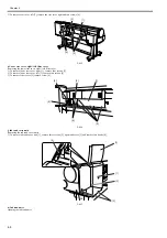
g) Left front cover

Removing the left front cover
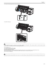
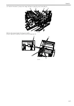
1) Raise the ejection guides.
2) Remove screw [1] and hook [2] to detach left front lower cover [3].

F-4-12

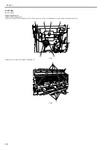
3) Remove two screws [1] to detach left front cover [2].

F-4-13

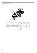
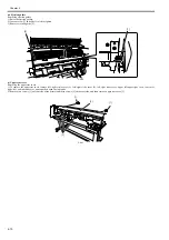
h) Rear cover right/Rear cover left

Removing the rear cover right/rear cover left
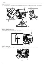
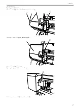
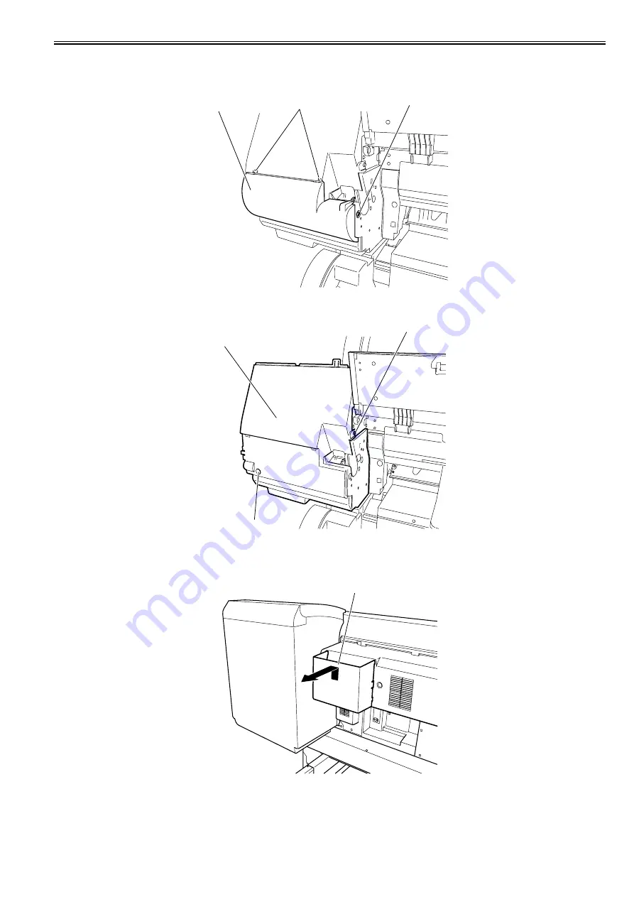
1) Remove the hook to remove accessory box [1].

F-4-14

2) To remove rear cover right [1], remove four screws [2].

[2]

[1]

[3]

[1]

[1]

[2]

[1]

Содержание iPF800 Series

Страница 1: ...Aug 13 2008 Service Manual iPF800 series ...

Страница 2: ......

Страница 3: ... need arises In the event of major changes in the contents of this manual over a long or short period Canon will issue a new edition of this manual The following paragraph does not apply to any countries where such provisions are inconsistent with local law Trademarks The product names and company names used in this manual are the registered trademarks of the individual companies Copyright This ma...

Страница 4: ...quiring care to avoid combustion fire Indicates an item prohibiting disassembly to avoid electric shocks or problems Indicates an item requiring disconnection of the power plug from the electric outlet Indicates an item intended to provide notes assisting the understanding of the topic in question Indicates an item of reference assisting the understanding of the topic in question Provides a descri...

Страница 5: ...sed to indicate Low The voltage value how ever differs from circuit to circuit In addition the asterisk as in DRMD indicates that the DRMD signal goes on when 0 In practically all cases the internal mechanisms of a microprocessor cannot be checked in the field Therefore the operations of the microprocessors used in the machines are not discussed they are explained in terms of from sensors to the i...

Страница 6: ......

Страница 7: ...nterface Specifications 1 22 1 5 Names and Functions of Components 1 23 1 5 1 Front 1 23 1 5 2 Front 1 25 1 5 3 Rear 1 26 1 5 4 Rear 1 27 1 5 5 Top Cover Inside 1 28 1 5 6 Carriage 1 29 1 5 7 Ink Tank Cover Inside 1 29 1 6 Basic Operation 1 30 1 6 1 Operation Panel 1 30 1 6 2 Main Menu 1 31 1 6 3 Main Menu 1 51 1 6 4 Basket Unit 1 71 1 7 Safety and Precautions 1 77 1 7 1 Safety Precautions 1 77 1 ...

Страница 8: ...2 3 2 4 Printhead 2 24 2 3 2 5 Purge Unit 2 25 2 3 2 6 Maintenance Cartridge 2 29 2 3 2 7 Air Flow 2 30 2 3 3 Paper Path 2 31 2 3 3 1 Outline 2 31 2 3 3 2 Paper Path 2 32 2 3 3 3 Cutter Unit 2 35 2 4 Printer Electrical System 2 36 2 4 1 Outline 2 36 2 4 1 1 Overview 2 36 2 4 1 2 Overview 2 38 2 4 2 Main Controller 2 40 2 4 2 1 Main controller PCB components 2 40 2 4 3 Carriage Relay PCB 2 42 2 4 3...

Страница 9: ...ck up Feed Unit 4 29 4 3 11 Purge Unit 4 32 4 3 12 Waste Ink Collection Unit 4 33 4 3 13 Ink Tank Unit 4 43 4 3 14 Multi Sensor 4 45 4 3 15 Linear Encoder Sensor 4 48 4 3 16 Head Management Sensor 4 49 4 3 17 PCBs 4 50 4 3 18 Opening the Cap Moving the Wiper Unit 4 51 4 3 19 Opening and closing ink supply valves 4 52 4 3 20 Draining the ink 4 53 4 4 Applying the Grease 4 54 4 4 1 Applying the Grea...

Страница 10: ...l 6 20 6 4 Service Tools 6 21 6 4 1 Tool List 6 21 Chapter 7 SERVICE MODE 7 1 Service Mode 7 1 7 1 1 Service Mode Operation 7 1 7 1 2 Map of the Service Mode 7 2 7 1 3 Details of Service Mode 7 8 7 1 4 Sample Printout 7 17 7 2 Special Mode 7 21 7 2 1 Special Modes for Servicing 7 21 Chapter 8 ERROR CODE 8 1 Outline 8 1 8 1 1 Outline 8 1 8 2 Warning Table 8 2 8 2 1 Warnings 8 2 8 3 Error Table 8 4 ...

Страница 11: ...Chapter 1 PRODUCT DESCRIPTION ...

Страница 12: ......

Страница 13: ... and Functions of Components 1 23 1 5 1 Front 1 23 1 5 2 Front 1 25 1 5 3 Rear 1 26 1 5 4 Rear 1 27 1 5 5 Top Cover Inside 1 28 1 5 6 Carriage 1 29 1 5 7 Ink Tank Cover Inside 1 29 1 6 Basic Operation 1 30 1 6 1 Operation Panel 1 30 1 6 2 Main Menu 1 31 1 6 3 Main Menu 1 51 1 6 4 Basket Unit 1 71 1 7 Safety and Precautions 1 77 1 7 1 Safety Precautions 1 77 1 7 1 1 Moving Parts 1 77 1 7 1 2 Adhesi...

Страница 14: ......

Страница 15: ...apable of output to either roll media or cut sheet F 1 1 T 1 1 1 Upper Cover 11 Release Lever 2 Ejection Guide 12 Maintenance Cartridge 3 Roll Holder Slot 13 Carrying Handles 4 Roll Holder 14 Maintenance Cartridge Cover 5 Ejection Support 15 Stand 6 Output Stacker 16 Stand L 7 Paper Feed Slot 17 Stand R 8 Holder Stopper 18 Stand Upper Stay 9 Ink Tank Cover 19 Leg cover 10 Operation Panel 20 Stoppe...

Страница 16: ...pter 1 1 2 F 1 2 T 1 2 1 Expansion Board Slot 5 Madia Take up Unit Connector 2 Ethernet Connector 6 Power Supply Connector 3 USB Port 7 Carrying Handles 4 Manual Pocket 8 Accessory Handles 3 2 1 4 5 6 7 8 ...

Страница 17: ...ther roll media or cut sheet F 1 3 T 1 3 1 Upper Cover 11 Maintenance Cartridge 2 Ejection Guide 12 Carrying Handles 3 Roll Holder Slot 13 Maintenance Cartridge Cover 4 Roll Holder 14 Stand 5 Cut Sheet Protective Cloth 15 Stand L 6 Paper Feed Slot 16 Stand R 7 Holder Stopper 17 Leg Cover 8 Ink Tank Cover 18 Stopper 9 Operation Panel 19 Lower Roll Unit 10 Release Lever 20 Lower Roll Unit Lever 1 9 ...

Страница 18: ...Chapter 1 1 4 F 1 4 T 1 4 1 Expansion Board Slot 5 Power Supply Connector 2 Ethernet Connector 6 Lower Roll Unit Connector 3 USB Port 7 Carrying Handles 4 Manual Pocket 8 Accessory Box 3 2 1 4 5 6 7 8 ...

Страница 19: ...inches 1117 6 mm Large ink tanks save the need for their replacement Uninterrupted printing from subtanks BK and MBK inks are loaded concurrently to eliminate the need for their replacement Media take up unit option is supported Media take up unit option can be mounted concurrently with a basket Durability will be added by maintenance kit Large LCD panel displays more information and makes operati...

Страница 20: ...hichever occurs earlier To install ink tanks open the right cover of the printer Ink tanks are furnished with a notch for preventing incorrect installation which will allow the tanks to be installed at the position marked in the right color and nowhere else Ink tanks are available in the four dye ink colors of black cyan magenta and yellow and the pigment ink color of mat black F 1 6 ...

Страница 21: ... holder accepts paper tubes having inside diameters of both 2 and 3 inches It is furnished with attachments for 2 and 3 inch diameter paper tubes The roll holder clamps the paper tube of a roll not exceeding 150 mm in outside diameter from the inside F 1 8 2 inch paper tube attachment F 1 9 3 inch paper tube attachment 1 F 1 10 3 inch paper tube attachment 2 F 1 11 ...

Страница 22: ...at the printer can be easily moved F 1 12 1 2 8 Stand 0020 6038 iPF810 It is a stand that puts the printer Equipped with casters so that the printer can be easily moved F 1 13 1 2 9 Wheeled output stacker 0020 5422 iPF810 iPF820 This is a output stacker on wheels that is attached to the front of the printer ...

Страница 23: ...overload protection feature to prevent accidents while taking up rolls The feature will shut down the motor automatically when an overload occurs while taking up a roll Additional features of the media take up unit include An adapter may be installed to support a 3 inch paper tube Rolls can be rewound by feeding them backward to visually check images Weight rollers varying in length to suit specif...

Страница 24: ...Chapter 1 1 10 Weight This weight consists of weight roll 7 pcs 1 weight flange 2 sets 2 and weight joint 3 F 1 16 2 1 2 2 1 3 1 2 ...

Страница 25: ...erved can be printed in as many copies as needed without having to use the host computer Reprinting after error occurrence If the printer encounters errors such as paper out while printing a print job it can resume the print operation as soon as the errors are cleared without needing its retransmission from the host computer Higher print work efficiency Print jobs can be printed selectively or in ...

Страница 26: ... are available in five colors mat black black cyan magenta and yellow Each is further available in two capacities 300ml and 700ml All ink tanks are usable for six months after unpacking Ink tanks that can be used with this printer are labeled A on their side F 1 19 Maintenance cartridge The expendable maintenance cartridge is the same as the one that comes with the printer F 1 20 ...

Страница 27: ...cations Media size Cut sheet Width 203mm 8 to 1118mm 44 Length 203mm 8 to 1600mm 63 Printable area Roll media Internal area excluding a 3 mm top bottom and left and right margins The printable area may vary with each type of paper media used Printable area Cut sheet Internal area excluding a 3 mm top margin a 23 mm bottom margin and 3 mm left and right margins The printable area may vary with each...

Страница 28: ...heeled output stacker Type Bubble jet large sized paper printer stand model Feeding system Roll media Manual front loading Cut sheet Paper tray front loading Feeding capacity Roll media 1 roll madia Outer diameter of roll 150 mm or less Cut sheet 1 sheet Delivery method Forward delivery face up Sheet delivery capability 1 sheet using the outout stacker of the stand Cutter Automatic cross cutter ro...

Страница 29: ...evel detection Yes Maintenance cartridge presence absence detection Yes Used ink tank full detection Yes Valve open closed detection Yes Detection functions Carriage system Printhead presence absence detection Yes Carriage position detection Yes Carriage home position detection Yes Printhead fixer lever open closed detection Yes Carriage temperature detection Yes Printhead height detection Yes Non...

Страница 30: ...gh 8 Bi directional 2400x1200 MBK Economy Bond Paper Office Document Standard 4 Bi directional 1200x1200 MBK Line Document Text Draft 2 Bi directional 1200x1200 MBK Standard 4 Bi directional 1200x1200 MBK Image Draft 2 Bi directional 1200x1200 MBK Standard 4 Bi directional 1200x1200 MBK High 8 Bi directional 2400x1200 MBK Universal Bond Paper Office Document Standard 4 Bi directional 1200x1200 MBK...

Страница 31: ...ional 1200x1200 MBK High 8 Bi directional 2400x1200 MBK Highest 12 Bi directional 2400x1200 MBK High Resolution Barrier Paper 180g Image Standard 4 Bi directional 1200x1200 MBK High 8 Bi directional 2400x1200 MBK Highest 12 Bi directional 2400x1200 MBK Matt Coated Paper 9171 120g Image Standard 4 Bi directional 1200x1200 MBK High 8 Bi directional 2400x1200 MBK Highest 12 Bi directional 2400x1200 M...

Страница 32: ... directional 2400x1200 PBK Highest 16 Bi directional 2400x1200 PBK Instant Dry Papers Glossy 200g Image Standard 6 Bi directional 1200x1200 PBK High 8 Bi directional 2400x1200 PBK Highest 16 Bi directional 2400x1200 PBK Instant Dry Papers Satin 200g Image Standard 6 Bi directional 1200x1200 PBK High 8 Bi directional 2400x1200 PBK Highest 16 Bi directional 2400x1200 PBK Photo Paper High Glossy 250g...

Страница 33: ...Standard 6 Bi directional 1200x1200 MBK High 8 Bi directional 2400x1200 MBK Highest 16 Bi directional 2400x1200 MBK Water Resistant Paper Art Canvas Image Standard 6 Bi directional 1200x1200 MBK High 8 Bi directional 2400x1200 MBK Highest 16 Bi directional 2400x1200 MBK Proofing Paper Proofing Paper Image Standard 6 Bi directional 1200x1200 PBK High 8 Bi directional 2400x1200 PBK Highest 16 Bi dir...

Страница 34: ...t 16 Bi directional 2400x1200 MBK Adhesive Synthetic Paper Image Standard 6 Bi directional 1200x1200 MBK High 8 Bi directional 2400x1200 MBK Highest 16 Bi directional 2400x1200 MBK Outdoor Polypropylene Durable Banner Image Standard 6 Bi directional 1200x1200 MBK High 8 Bi directional 2400x1200 MBK Highest 16 Bi directional 2400x1200 MBK Adhesive Matt Paper High Resolution Graphic Paper Self ADH I...

Страница 35: ...tional 2400x1200 PBK Highest 16 Bi directional 2400x1200 PBK SPECIAL 6 Image Standard 6 Bi directional 1200x1200 MBK High 8 Bi directional 2400x1200 MBK Highest 16 Bi directional 2400x1200 MBK SPECIAL 7 Image Standard 6 Bi directional 1200x1200 MBK High 8 Bi directional 2400x1200 MBK Highest 16 Bi directional 2400x1200 MBK SPECIAL 8 Image Standard 6 Bi directional 1200x1200 MBK High 8 Bi direction...

Страница 36: ... V 100Base TX 0 95 to 1 05 V 4 Interface cable Category 5 UTP or FTP cable 100 m or shorter Compliant with ANSI EIA TIA 568A or ANSI EIA TIA 568B 5 Interface connector Printer side Compliant with IEEE802 3 ANSI X3 263 ISO IEC60603 7 c IEEE1394 option 1 Interface type Interface compliant with IEEE1394 1995 P1394a Version 2 0 2 Data transfer system Asynchronous transfer 3 Signal level Input Differen...

Страница 37: ... paper retainer Pull up this lever to front to load paper 11 Maintenance cartridge Collects inks that have been used for maintenance services such as head cleaning 12 Carrying handle The carrying handle is located on both left and right sides of the bottom Allow a team of six persons to carry the printer 13 Maintenance cartridge cover Open this cover to replace the maintenance cartridge 14 Stand T...

Страница 38: ...Chapter 1 1 24 Hold this lever to pull out the lower roll unit ...

Страница 39: ...el 11 Release lever Releases the paper retainer Pull up this lever to front to load paper 12 Maintenance cartridge Collects inks that have been used for maintenance services such as head cleaning 13 Carrying handle The carrying handle is located on both left and right sides of the bottom Allow a team of six persons to carry the printer 14 Maintenance cartridge cover Open this cover to replace the ...

Страница 40: ... port Insert a USB cable into this port Hi Speed USB ready 4 Manual pocket Have the printer manual stowed in this pocket 5 Power connector Insert the power cord into this connector 6 Lower roll unit connector Insert the lower roll unit cable into this connector 7 Carrying handle The carrying handle is located on both left and right sides of the bottom Allow a team of six persons to carry the print...

Страница 41: ...t a USB cable into this port Hi Speed USB ready 4 Manual pocket Have the printer manual stowed in this pocket 5 Media take up unit connector Insert the cable a media take up unit option into this connector 6 Power Supply Connector Connect the power cord to this connector 7 Carrying handle The carrying handle is located on both left and right sides of the bottom Allow a team of six persons to carry...

Страница 42: ...sening during travel 7 Borderless printing ink reservoir Receives inks overflowing the outside of the paper during borderless printing 8 Cleaner brush Sweeps off paper dust from the platen surface when cleaning the inside of the upper cover 9 Cutter rail The part the cutter unit traverses to cut paper 10 Cutter unit A round cutter for cutting paper automatically 11 Linear scale A principal part fo...

Страница 43: ...nk Move this lever up and down to replace the ink tank To open raise the stopper of the lever until it won t go farther and then push it to the front To close depress the stopper until it clicks 3 Ink lamp red Indicates the status of the ink tank when the ink tank cover is opened as follows On An ink tank is properly loaded Off No ink tank is loaded or the remaining ink sensor is disabled Slow bli...

Страница 44: ...he printer is in offline mode to manually feed roll media Press this button when the printer is in menu mode to view the next item or setting 12 button Press this button when the printer is in menu mode to view the menu at the lower level If NEXT on display the guidance screen can be moved forward 13 Load Eject button Guidance offers a visual clue to loading replacing removing paper Press this but...

Страница 45: ... time and a menu related to parameters such as a message language 1 Main menu operations a How to enter the Main menu To enter the Main menu press the Menu button on the operation panel b How to exit the Main menu To exit the Main menu press the Online button c Buttons used with the Main menu Selecting menus and parameters or button Going to the next lower level menu button Going to the next highe...

Страница 46: ...p Reel 10 Disable Enable Media Menu Cut Sheet Type Plain Paper 5 Plain Paper HQ 5 Plain Paper HG 5 Recycled Coated 5 Coated Paper 5 HW Coated 5 Ex HW Coated 5 Premium MatteP 5 Glossy Photo 5 Semi Gl Photo 5 HW SemiGl Photo 5 HW SemiGl Photo2 5 Poster Semi Gl 5 Syn Paper 5 Adh Syn Paper 5 Backlit Film 5 Backprint Film 5 Flame Res Cloth 5 Fabric Banner 5 ThinFab Banner2 5 Proofing Paper 5 News Proof...

Страница 47: ... Paper 5 CAD Matte Film 5 CAD Clear Film 5 Special Here the number is 1 to 10 5 Roll Media Type Plain Paper 5 Plain Paper HQ 5 Plain Paper HG 5 Recycled Coated 5 Coated Paper 5 HW Coated 5 Ex HW Coated 5 Premium MatteP 5 Glossy Photo 5 Semi Gl Photo 5 HW Glossy Photo2 5 HW SemiGl Photo2 5 Poster Semi Gl 5 Syn Paper 5 Adh Syn Paper 5 Backlit Film 5 Backprint Film 5 Flame Res Cloth 5 Fabric Banner 5...

Страница 48: ... Coated 5 CAD Trace Paper 5 CAD Matte Film 5 CAD Clear Film 5 Special Here the number is 1 to 10 5 Roll Length Set 1 2 m 16 feet 16 Chk Remain Roll Off On Paper Details The paper type is displayed here 5 Roll DryingTime Off 30 sec 1 min 3 min 5 min 10 min 30 min 60 min Scan Wait Time Off 1 sec 3 sec 5 sec 7 sec 9 sec Feed Priority Automatic Band Joint Print Length Adjust Length A 0 70 0 00 0 70 Ad...

Страница 49: ... Automatic Fixed CutDustReduct Off On NearEnd Sht Mrgn 3mm 20mm Return Defaults No Yes Job Management Print Job Job List Choose a print job Delete Preempt Jobs Stored Job Mailbox List Enter a password if one has been set Job List Print Delete Print Job List No Yes Job Log Choose from information about the latest three print jobs Document Name User Name Page Count Job Status OK CANCELED Print Start...

Страница 50: ... Quality Draft Standard High Print Economy Off On Input Resolution 600dpi 300dpi Paper Source Automatic Roll Paper Cut Sheet Conserve Paper Off On Line Cap Software Rounded Smoothing Software Smooth Line Width 1dot 2dot 3dot 4dot 5dot 6dot 7dot ThickenFineLines Off On AdjustFaintLines Off On Auto Rotate Off On Nesting Use Nesting Off On Nesting WaitTime 1 11min Cut Lines Off On On the Fly Off On ...

Страница 51: ...d Adj No Yes Auto Print Off On Manual Head Adj 12 No Yes Auto Band Adj Standard Adj No Yes Advanced Adj No Yes Manual Band Adj No Yes Adjust Length 3 A High No Yes B Standard Draft No Yes Head Inc Adj No Yes Interface Setup EOP Timer 10 sec 30 sec 1 min 2 min 5 min 10 min 30 min 60 min TCP IP IP Mode Automatic Manual Protocol 4 DHCP On Off ...

Страница 52: ...W 0 0 0 0 to 255 255 255 255 NetWare NetWare On Off Frame Type 6 Auto Detect Ethernet 2 Ethernet 802 2 Ethernet 802 3 Ethernet SNAP Print Service 6 BinderyPServer RPrinter NDSPServer NPrinter AppleTalk On Off Ethernet Driver Auto Detect On Off Comm Mode 7 Half Duplex Full Duplex Ethernet Type 7 10 Base T 100 Base TX Spanning Tree Not Use Use MAC Address 000085XXXXXX Ext Interface No IEEE1394 Init ...

Страница 53: ...evel 3 System Setup Warning Buzzer Off On Detect Mismatch Pause Warning None Skip Take Up Err 10 Off On Keep Media Size Off On Paper Size Basis Sht Selection 1 ISO A3 13 x19 Super B Sht Selection 2 ISO B1 28 x40 ANSI F Noz Check Freq Off 1 page 10 pages Automatic CarriageScanWdth Automatic Fixed Sleep Timer 5 min 10 min 15 min 20 min 30 min 40 min 50 min 60 min 240 min ...

Страница 54: ...thens Cairo 3 Moscow 4 Eerevan Baku 5 Islamabad 6 Dacca 7 Bangkok 8 Hong Kong 9 Tokyo Seoul 10 Canberra 11 NewCaledonia 12 Wellington 12 Eniwetok 11 Midway is 10 Hawaii AHST 9 Alaska AKST 8 Oregon PST 7 Arizona MST 6 Texas CST 5 NewYork EST 4 Santiago 3 Buenos Aires 2 1 Cape Verde Date Format yyyy mm dd dd mm yyyy mm dd yyyy Date Time Date yyyy mm dd 8 Time hh mm ...

Страница 55: ...he Media Take up Unit is attached 12 Displayed if paper is loaded in the tray 13 Available if Take up Reel is Enable roll paper is loaded and you have not executed Auto Feed for the loaded roll 14 This menu is only displayed during printing 16 Not displayed if a roll or a sheet has been fed First Level Second Level Third Level Fourth Level Fifth Level System Setup Language Japanese English Francai...

Страница 56: ...the main menu during printing is as follows T 1 18 First Level Second Level Third Level Fourth Level Fifth Level Menu Durng Prtng Head Cleaning Head Cleaning A Head Cleaning B Fine Band Adj 5 to 5 Information System Info Error Log 1 xxxxxxxx xxxx 2 xxxxxxxx xxxx ...

Страница 57: ...s for making prints using GL2 Adjust Printer Adjust the Printhead alignment or amount of feed by printing a test pattern Interface Setup Configure the EOP timer and network settings Maintenance Access maintenance settings when replacing the Printhead or preparing to move the printer System Setup Specify the printer system settings including the date format and display language Test Print Choose St...

Страница 58: ...er printing quality at the leading edge Note that if you choose 5mm it may lower the printing quality at the leading edge and affect feeding accuracy The printed surface may be scratched and ink may adhere to the leading edge It may also cause the Platen to become soiled Cut Speed Choose the cutting speed If you use adhesive paper choosing Slow helps prevent adhesive from sticking to the cutter an...

Страница 59: ...in the most recently printed job User Name Displays the name of the user who has transmitted the job Page Count Displays the number of sheets of the job Job Status Displays the result of processing of the job Print Start Time Displays the time at which the job started printing Print End Time Displays the time at which the job finished printing Print Time Displays the time spent printing the job Pr...

Страница 60: ...int for data that does not have a line width specified The line width is expressed in increments of 300 dpi ThickenFineLines Select On to print thin lines clearly AdjustFaintLines If thin lines print in a tint of color varied from other patterns selecting Off may provide the print result as intended though the thin lines may print interrupted depending on the color Auto Rotate If a document has it...

Страница 61: ...nd Adj Standard Adj Choose Yes to have the printer print and read a band adjustment test pattern for automatic adjustment of the feed amount Advanced Adj Choose this option when using paper other than genuine Canon paper or paper for purposes other than checking output Choose Yes to have the printer print and read a band adjustment test pattern for automatic adjustment of the feed amount Note that...

Страница 62: ...fy the communication method To apply your changes choose Register Setting Choose On for automatic configuration of the LAN communication protocol Choose Off to use settings values of Comm Mode and Ethernet Type Comm Mode Choose the LAN communication method Ethernet Type Choose the LAN transfer rate Spanning Tree Choose whether spanning tree packets are supported over the LAN MAC Address Displays t...

Страница 63: ...ozzle clogging Choose 1 page to check once per printed page Choose 10 pages to check once per ten printed pages Choose Automatic to have the printer automatically adjust the timing for checks based on the frequency of nozzle use CarriageScanWdth Set the scan width of the carriage for printing Select Automatic to move the carriage to meet the width of the loaded paper Selecting Fixed will reduce st...

Страница 64: ...he version of the printer and firmware Boot Displays the version of the boot ROM MIT Displays the version of the MIT database format s n Displays the printer s serial number MAC Displays the MAC address of the printer IP Displays the printer IP address Error Log Displays the most recent error messages up to two ...

Страница 65: ... time and a menu related to parameters such as a message language 1 Main menu operations a How to enter the Main menu To enter the Main menu press the Menu button on the operation panel b How to exit the Main menu To exit the Main menu press the Online button c Buttons used with the Main menu Selecting menus and parameters or button Going to the next lower level menu button Going to the next highe...

Страница 66: ...Media Menu Cut Sheet Type Plain Paper 5 Plain Paper HQ 5 Plain Paper HG 5 Recycled Coated 5 Coated Paper 5 HW Coated 5 Ex HW Coated 5 Premium MatteP 5 Glossy Photo 5 Semi Gl Photo 5 HW SemiGl Photo 5 HW SemiGl Photo2 5 Poster Semi Gl 5 Syn Paper 5 Adh Syn Paper 5 Backlit Film 5 Backprint Film 5 Flame Res Cloth 5 Fabric Banner 5 ThinFab Banner2 5 Proofing Paper 5 News Proof 1 5 News Proof 2 5 FineA...

Страница 67: ...CAD Matte Film 5 CAD Clear Film 5 Special Here the number is 1 to 10 5 Roll1 Uppr Type Roll2 Lwr Type 1 2 Plain Paper 5 Plain Paper HQ 5 Plain Paper HG 5 Recycled Coated 5 Coated Paper 5 HW Coated 5 Ex HW Coated 5 Premium MatteP 5 Glossy Photo 5 Semi Gl Photo 5 HW Glossy Photo2 5 HW SemiGl Photo2 5 Poster Semi Gl 5 Syn Paper 5 Adh Syn Paper 5 Backlit Film 5 Backprint Film 5 Flame Res Cloth 5 Fabri...

Страница 68: ...d Coated 5 CAD Trace Paper 5 CAD Matte Film 5 CAD Clear Film 5 Special Here the number is 1 to 10 5 Roll1 Uppr Lngth Roll2 Lwr Lngth 1 2 m 16 feet 16 Chk Remain Roll Off On Paper Details The paper type is displayed here 5 Roll DryingTime Off 30 sec 1 min 3 min 5 min 10 min 30 min 60 min Scan Wait Time Off 1 sec 3 sec 5 sec 7 sec 9 sec Feed Priority Automatic Band Joint Print Length Adjust Length A...

Страница 69: ... Automatic Fixed CutDustReduct Off On NearEnd Sht Mrgn 3mm 20mm Return Defaults No Yes Job Management Print Job Job List Choose a print job Delete Preempt Jobs Stored Job Mailbox List Enter a password if one has been set Job List Print Delete Print Job List No Yes Job Log Choose from information about the latest three print jobs Document Name User Name Page Count Job Status OK CANCELED Print Start...

Страница 70: ... Quality Draft Standard High Print Economy Off On Input Resolution 600dpi 300dpi Paper Source Automatic Roll Paper Cut Sheet Conserve Paper Off On Line Cap Software Rounded Smoothing Software Smooth Line Width 1dot 2dot 3dot 4dot 5dot 6dot 7dot ThickenFineLines Off On AdjustFaintLines Off On Auto Rotate Off On Nesting Use Nesting Off On Nesting WaitTime 1 11min Cut Lines Off On On the Fly Off On ...

Страница 71: ...d Adj No Yes Auto Print Off On Manual Head Adj 12 No Yes Auto Band Adj Standard Adj No Yes Advanced Adj No Yes Manual Band Adj No Yes Adjust Length 3 A High No Yes B Standard Draft No Yes Head Inc Adj No Yes Interface Setup EOP Timer 10 sec 30 sec 1 min 2 min 5 min 10 min 30 min 60 min TCP IP IP Mode Automatic Manual Protocol 4 DHCP On Off ...

Страница 72: ...W 0 0 0 0 to 255 255 255 255 NetWare NetWare On Off Frame Type 6 Auto Detect Ethernet 2 Ethernet 802 2 Ethernet 802 3 Ethernet SNAP Print Service 6 BinderyPServer RPrinter NDSPServer NPrinter AppleTalk On Off Ethernet Driver Auto Detect On Off Comm Mode 7 Half Duplex Full Duplex Ethernet Type 7 10 Base T 100 Base TX Spanning Tree Not Use Use MAC Address 000085XXXXXX Ext Interface No IEEE1394 Init ...

Страница 73: ...g Buzzer Off On Detect Mismatch Pause Warning None Keep Media Size Off On Paper Size Basis Sht Selection 1 ISO A3 13 x19 Super B Sht Selection 2 ISO B1 28 x40 ANSI F Roll Switching Size Optimized No SizeOptimized TrimEdge Reload Automatic Off On Noz Check Freq Off 1 page 10 pages Automatic CarriageScanWdth Automatic Fixed Sleep Timer 5 min 10 min 15 min 20 min 30 min 40 min 50 min 60 min 240 min ...

Страница 74: ...thens Cairo 3 Moscow 4 Eerevan Baku 5 Islamabad 6 Dacca 7 Bangkok 8 Hong Kong 9 Tokyo Seoul 10 Canberra 11 NewCaledonia 12 Wellington 12 Eniwetok 11 Midway is 10 Hawaii AHST 9 Alaska AKST 8 Oregon PST 7 Arizona MST 6 Texas CST 5 NewYork EST 4 Santiago 3 Buenos Aires 2 1 Cape Verde Date Format yyyy mm dd dd mm yyyy mm dd yyyy Date Time Date yyyy mm dd 8 Time hh mm ...

Страница 75: ...ailable only if NetWare is On 8 Follows the setting in Date Format 12 Displayed if paper is loaded in the tray 14 This menu is only displayed during printing 16 Not displayed if a roll or a sheet has been fed First Level Second Level Third Level Fourth Level Fifth Level System Setup Language Japanese English Francais Italiano Deutsch Espanol Pyccknn Chinese Korea Contrast Adj 4 to 4 Reset PaprSetn...

Страница 76: ...the main menu during printing is as follows T 1 39 First Level Second Level Third Level Fourth Level Fifth Level Menu Durng Prtng Head Cleaning Head Cleaning A Head Cleaning B Fine Band Adj 5 to 5 Information System Info Error Log 1 xxxxxxxx xxxx 2 xxxxxxxx xxxx ...

Страница 77: ...attern Interface Setup Configure the EOP timer and network settings Maintenance Access maintenance settings when replacing the Printhead or preparing to move the printer System Setup Specify the printer system settings including the date format and display language Test Print Choose Status Print to print information about the printer Choose Media Details to print the paper settings as specified in...

Страница 78: ...er printing quality at the leading edge Note that if you choose 5mm it may lower the printing quality at the leading edge and affect feeding accuracy The printed surface may be scratched and ink may adhere to the leading edge It may also cause the Platen to become soiled Cut Speed Choose the cutting speed If you use adhesive paper choosing Slow helps prevent adhesive from sticking to the cutter an...

Страница 79: ...in the most recently printed job User Name Displays the name of the user who has transmitted the job Page Count Displays the number of sheets of the job Job Status Displays the result of processing of the job Print Start Time Displays the time at which the job started printing Print End Time Displays the time at which the job finished printing Print Time Displays the time spent printing the job Pr...

Страница 80: ...int for data that does not have a line width specified The line width is expressed in increments of 300 dpi ThickenFineLines Select On to print thin lines clearly AdjustFaintLines If thin lines print in a tint of color varied from other patterns selecting Off may provide the print result as intended though the thin lines may print interrupted depending on the color Auto Rotate If a document has it...

Страница 81: ...nd Adj Standard Adj Choose Yes to have the printer print and read a band adjustment test pattern for automatic adjustment of the feed amount Advanced Adj Choose this option when using paper other than genuine Canon paper or paper for purposes other than checking output Choose Yes to have the printer print and read a band adjustment test pattern for automatic adjustment of the feed amount Note that...

Страница 82: ...fy the communication method To apply your changes choose Register Setting Choose On for automatic configuration of the LAN communication protocol Choose Off to use settings values of Comm Mode and Ethernet Type Comm Mode Choose the LAN communication method Ethernet Type Choose the LAN transfer rate Spanning Tree Choose whether spanning tree packets are supported over the LAN MAC Address Displays t...

Страница 83: ...ed Choose Automatic to cut it when the paper at the standby position during two days or more has loaded Noz Check Freq Specify the timing for automatic checks of nozzle clogging Choose 1 page to check once per printed page Choose 10 pages to check once per ten printed pages Choose Automatic to have the printer automatically adjust the timing for checks based on the frequency of nozzle use Carriage...

Страница 84: ...he version of the printer and firmware Boot Displays the version of the boot ROM MIT Displays the version of the MIT database format s n Displays the printer s serial number MAC Displays the MAC address of the printer IP Displays the printer IP address Error Log Displays the most recent error messages up to two ...

Страница 85: ...d one sheet When printing multiple pages remove each sheet after it is printed Before using the Output Stacker remove the Rewind Spool If you do not it may prevent printed documents from being held correctly and it they may be scratched a Using the Output Stacker in the position for ejection in the front of the printer You can also set the Output Stacker to the following position when printing ban...

Страница 86: ...ently to release the lock lower the stacker toward the front and push it all the way back F 1 31 2 Remove the front Basket Rod from the left and right Basket Rods and remove the back Basket Rod and the black cord from the Rod Holder F 1 32 ...

Страница 87: ... Adapter leaving the Rod Holder attached and put it in front of the printer F 1 33 4 Pull out the Basket Hooks from the left and right side of the Ejection Guide F 1 34 5 Attach the Basket Rod to the Basket Hooks so that the white tag of the Basket Cloth is on the left side F 1 35 ...

Страница 88: ...d to the Rod Holder F 1 36 b Stowing the Output Stacker Stow the Output Stacker if you will use the Media Take up Unit or if you will not use the Output Stacker for an extended period 1 Lift the front Basket Rod gently to release the lock lower the stacker toward the front and push it all the way back F 1 37 ...

Страница 89: ...Basket Rod from the left and right Basket Rods Roll up the Basket Cloth and put it at the back of the Bottom Stand Stay F 1 38 F 1 39 Arrange the Basket Cloth and Basket Rod so they do not interfere with the Media Take up Sensor F 1 40 ...

Страница 90: ...Chapter 1 1 76 3 Push in the left and right Basket Rods toward the back all the way until they stop F 1 41 ...

Страница 91: ...driven purge unit To prevent accidents the upper cover of the printer is locked during printing so that itdoes not open If the upper cover is opened in the online offline mode the carriage motor feed motor and other driving power supplies are turned off F 1 42 T 1 50 1 Carriage belt 8 Feed assembly 2 Pinch roller 9 Feed motor 3 Carriage 10 Roll media pick up drive unit 4 Ink tube unit 11 Lower rol...

Страница 92: ...to each unit F 1 43 T 1 51 Although the ink is not harmful to the human body it contains organic solvents Avoid getting the ink in your mouth or eyes Flush well with water and see a doctor if contact occurs In case of accidental ingestion of a large quantity call a doctor immediately Since this ink contains pigment stains will not come out of clothing 1 Maintenance cartridge 6 Carriage 2 Purge uni...

Страница 93: ...llected in the printer by the airflow However uncollected ink mist may stain the platen unit carriage unit main rail unit external unit or purge unit These stains may soil the print media or hands and clothes when servicing the printer wipe them off carefully with a soft well wrung damp cloth F 1 44 T 1 52 1 Purge unit 3 Platen unit Carriage unit Main rail unit 2 Upper cover 1 2 3 ...

Страница 94: ...ocated on the upper right cover When servicing the printer with the cover removed be extremely careful to avoid electric shock and shorting contacts F 1 45 T 1 53 1 Operation panel 8 Power supply PCB 2 Carriage relay PCB 9 Main controller PCB 3 Head relay PCB 10 Ethernet connector 4 AC inlet 11 USB port 5 Lower roll unit connector iPF820 12 Media take up relay PCB iPF810 6 Lower roll unit relay PC...

Страница 95: ...46 T 1 54 2 Capping The printer will perform the capping operation when printing has ended or during standby due to an error in order to protect the printhead and avoid ink leakage If the power cord is accidentally unplugged turn off the Power button reconnect the power cord and then turn on the Power button Confirm that the printer starts up properly and enters to the Online or Offline status and...

Страница 96: ...g it Otherwise the ink ingredients may precipitate and degrade the print quality To prevent foreign matter from entering the ink port installed the unpacked ink tank in the printer immediately 2 Handling the Ink Tank To prevent foreign matter from entering the ink flow path and causing ink suction and printing problems never touch the ink port and contacts of the ink tank When you press down the i...

Страница 97: ...ange their electrical characteristics In particular never touch the printhead contacts 1 F 1 48 2 Fixing the Carriage After completion of printing the carriage is mechanically locked by the lock arm in the purge unit at the same moment the printhead is capped Before transporting the printer secure the carriage at its home position using belt stoppers 1 so that the carriage does not become separate...

Страница 98: ...that the waste ink does not splash when you remove the used maintenance cartridge from the printer MEMO This printer has an EEPROM in the maintenance cartridge and the maintenance cartridge status is controlled by the main controller PCB which reads and writes the content of that EEPROM Therefore initializing the counter information will not be needed when the maintenance cartridge is replaced 5 R...

Страница 99: ...lize clear the parts counter information For the consumable parts see Maintenance Consumable Parts You cannot check the counter information once it is initialized cleared Be careful not to initialize the counter information before checking it You cannot modify the counter information from the operation panel 1 7 3 2 Confirming the Firmware Version 0013 5945 iPF810 iPF820 Firmware has been download...

Страница 100: ...Chapter 1 1 86 ...

Страница 101: ...Chapter 2 TECHNICAL REFERENCE ...

Страница 102: ......

Страница 103: ...nk Tank Unit 2 19 2 3 2 3 Carriage Unit 2 21 2 3 2 3 1 Functions of Carriage Unit 2 21 2 3 2 3 2 Structure of Carriage Unit 2 22 2 3 2 4 Printhead 2 24 2 3 2 4 1 Structure of Printhead 2 24 2 3 2 5 Purge Unit 2 25 2 3 2 5 1 Functions of Purge Unit 2 25 2 3 2 5 2 Structure of Purge Unit 2 27 2 3 2 6 Maintenance Cartridge 2 29 2 3 2 6 1 Maintenance Cartridge 2 29 2 3 2 7 Air Flow 2 30 2 3 2 7 1 Air ...

Страница 104: ...dge Relay PCB 2 44 2 4 6 1 Maintenance cartridge relay PCB components 2 44 2 4 7 Power Supply 2 45 2 4 7 1 Power supply block diagram 2 45 2 5 Detection Functions with Sensors 2 46 2 5 1 Sensors for covers 2 46 2 5 2 Ink passage system 2 47 2 5 3 Carriage system 2 49 2 5 4 Paper path system 2 51 2 5 5 Media take up Unit 2 53 2 5 6 Others 2 53 ...

Страница 105: ...r Feed motor Lift motor Purge motor Valve motor Cutter motor Roll media pick up motor Pinch roller pressure motor HP maintenance jet pump motor Carriage HP sensor Pump encoder sensor Pump cam sensor Media sensor Head management sensor Feed roller encoder sensor Feed roller HP sensor Valve open closed detection sensor Agitation cam sensor Temperature humidity detection sensor Lift cam sensor HP mai...

Страница 106: ...troller PCB BAT 801 Lithium battery Operation panel PCB Maintenance cartridge relay PCB Maintenance cartridge ROM PCB Ink tank Ink tank ROM PCB Ink detection sensor Sensors Switches Motor Solenoids Clutches Fans Solenoids Clutches Carriage motor Feed motor Lift motor Purge motor Valve motor Cutter motor Roll media pick up motor Pinch roller pressure motor HP maintenance jet pump motor Carriage HP ...

Страница 107: ...unted on the printheads and the printer temperature from the latch IC on the carriage board and transmit them to the ASIC IC1 The ASIC IC1 also receives mask pattern data from the firmware installed in flash ROM f The ASIC IC1 converts the image data synthesized with the mask pattern to data associated with the printhead information and the printer temperature trans mitting the data to the printhe...

Страница 108: ...e selected split in 40 20 or 10 nozzle blocks according to the Block Enable information in the even numbered nozzle data and odd num bered nozzle data Each selected block of nozzles is impressed with a Heat Enable signal generated with variable pulse widths according to the head rank head temperature and printer temperature for optimized ink discharges The nozzles are driven by heater boards in th...

Страница 109: ...ng signal internal signal which is generated by dividing the ENCODER_A signal detected at the 150 dpi timing into 16 equal sections Printing in the forward direction is triggered at the leading edge of the detection signal ENCODER_A Printing in the backward direction is carried out the same way as printing in the forward direction but at the trailing edge of the detection signal ENCODER_A when the...

Страница 110: ...k Media feed system initialization Recovery system initialization Carriage position initialization Remaining ink level detection Waste ink level detection Power on automatic recovery operation Capping Waiting for print operation Initialization of software Initialization of various devices Engine status check Engine startup status check Previous power off status check etc Printhead installation sta...

Страница 111: ...g operation and shuts down immediately Since printhead capping may or may not have been carried out properly reconnect the power cord to the wall out and turn on the power switch Making sure that the printer has entered online mode turn off the power switch 1 Power off sequence F 2 7 Power button OFF If media remains it is ejected even when printing is in progress Media ejection Power off automati...

Страница 112: ...ng Even in the same mode the printer operates in a different way depending on the media setting made using the printer driver a Draft mode In the draft mode image data is thinned out and a single band equivalent to the width of a nozzle array is printed using two paths To use this mode select Draft under Print Quality in the printer driver b Standard mode In the standard mode a single band equival...

Страница 113: ...h 8 Bi directional 2400x1200 MBK Economy Bond Paper Office Document Standard 4 Bi directional 1200x1200 MBK Line Document Text Draft 2 Bi directional 1200x1200 MBK Standard 4 Bi directional 1200x1200 MBK Image Draft 2 Bi directional 1200x1200 MBK Standard 4 Bi directional 1200x1200 MBK High 8 Bi directional 2400x1200 MBK Universal Bond Paper Office Document Standard 4 Bi directional 1200x1200 MBK ...

Страница 114: ...ional 1200x1200 MBK High 8 Bi directional 2400x1200 MBK Highest 12 Bi directional 2400x1200 MBK High Resolution Barrier Paper 180g Image Standard 4 Bi directional 1200x1200 MBK High 8 Bi directional 2400x1200 MBK Highest 12 Bi directional 2400x1200 MBK Matt Coated Paper 9171 120g Image Standard 4 Bi directional 1200x1200 MBK High 8 Bi directional 2400x1200 MBK Highest 12 Bi directional 2400x1200 M...

Страница 115: ... directional 2400x1200 PBK Highest 16 Bi directional 2400x1200 PBK Instant Dry Papers Glossy 200g Image Standard 6 Bi directional 1200x1200 PBK High 8 Bi directional 2400x1200 PBK Highest 16 Bi directional 2400x1200 PBK Instant Dry Papers Satin 200g Image Standard 6 Bi directional 1200x1200 PBK High 8 Bi directional 2400x1200 PBK Highest 16 Bi directional 2400x1200 PBK Photo Paper High Glossy 250g...

Страница 116: ...Standard 6 Bi directional 1200x1200 MBK High 8 Bi directional 2400x1200 MBK Highest 16 Bi directional 2400x1200 MBK Water Resistant Paper Art Canvas Image Standard 6 Bi directional 1200x1200 MBK High 8 Bi directional 2400x1200 MBK Highest 16 Bi directional 2400x1200 MBK Proofing Paper Proofing Paper Image Standard 6 Bi directional 1200x1200 PBK High 8 Bi directional 2400x1200 PBK Highest 16 Bi dir...

Страница 117: ...t 16 Bi directional 2400x1200 MBK Adhesive Synthetic Paper Image Standard 6 Bi directional 1200x1200 MBK High 8 Bi directional 2400x1200 MBK Highest 16 Bi directional 2400x1200 MBK Outdoor Polypropylene Durable Banner Image Standard 6 Bi directional 1200x1200 MBK High 8 Bi directional 2400x1200 MBK Highest 16 Bi directional 2400x1200 MBK Adhesive Matt Paper High Resolution Graphic Paper Self ADH I...

Страница 118: ...tional 2400x1200 PBK Highest 16 Bi directional 2400x1200 PBK SPECIAL 6 Image Standard 6 Bi directional 1200x1200 MBK High 8 Bi directional 2400x1200 MBK Highest 16 Bi directional 2400x1200 MBK SPECIAL 7 Image Standard 6 Bi directional 1200x1200 MBK High 8 Bi directional 2400x1200 MBK Highest 16 Bi directional 2400x1200 MBK SPECIAL 8 Image Standard 6 Bi directional 1200x1200 MBK High 8 Bi direction...

Страница 119: ... status Printing resumes when the printhead radiates naturally to cool down to below a predetermined temperature or when 30 seconds or longer have elapsed since the detection of the temperature higher than the protection temperature Protection level 2 If the head temperature sensor DI sensor detects a temperature higher than the abnormal temperature the printer shuts down the print operation immed...

Страница 120: ... in the common box are deleted from the oldest one in sequence Print jobs can be simply stored in the personal box without printing Print jobs stored in the common box can be moved to the personal box 4 Preserved job handling Print jobs stored in the personal box or common box can be printed from the operation panel 5 Job queue handling Multiple jobs queued for print can be handled including the r...

Страница 121: ...a printhead mounted on carriage unit 2 purge assembly 3 and maintenance cartridge 4 Its func tions are to supply circulate and suck inks and more The paper pass comprises an feed assembly 5 upper roll media pick up assembly 6 a lower roll media pick up assembly 7 and more to feed paper in three different ways and transport and eject the paper lower roll unit is iPF820 only A summary description of...

Страница 122: ...that inks are constantly feeding to the printhead under the negative pressure of the nozzle assembly caused by discharging inks Further waste inks sucked in a cleaning operation and inks from the maintenance jet tray flow into the maintenance cartridge Opening all the ink passages by opening both the ink supply valve and the printhead fixer lever with an ink tank yet to be installed while an ink t...

Страница 123: ...nk port sealed by a rubber plug linking the ink passage of the ink to the printer c Air passage Depressing the ink tank fixer lever on the printer would cause an open hollow needle to pierce the air passage sealed by a rubber plug releasing the internal pressure of the ink tank to keep it constant d Notches for preventing incorrect installation Ink tanks are furnished with a notch for preventing i...

Страница 124: ...the ink tube on the ink tank is released during replacement of the ink tank The ink supply valve is opened and closed by a valve open close mechanism The ink tank unit consists of a tank base into which five color ink tanks are assembled and ink tubes for six colors two occupied by MBK Each color specific ink supply valve is linked to the action of a valve cam so the ink supply valves will open an...

Страница 125: ...t generation as the carriage height increases or to head rubbing as the carriage height decreases To maintain an acceptable carriage height the lift motor is driven according to the selected paper type feeding method print conditions borderless printing prior itized picture quality environmental condition temperature humidity and multi sensor measurements to automatically adjust the separation bet...

Страница 126: ...f the carriage belt The carriage home position or the capping position is detected by the sensor flag on the right side of the carriage and the photointerrupter based carriage HP sensor on the right side of the printer When the linear scale position is set as a reference home position for use in subsequent position control operations the carriage motor is driven by a control signal generated from ...

Страница 127: ...lculated during carriage height measurement by measuring the intensity of light reflected upon the white plate Service mode SERVICE MODE ADJUST GAP CALIB h Rail cleaner The shaft cleaner located in the right side of the carriage helps keep the main rail clean i Internal unit temperature sensor One thermistor is installed on the head relay PCB on the back of the head holder to detect the internal u...

Страница 128: ...tervals F 2 14 b Nozzle assembly structure Inks supplied from the ink tanks are filtered through a mesh ink filter before being sent to the nozzle assembly Each nozzle train is supplied with an ink from the common nozzle chamber A head drive current subsequently flowing through the nozzle heater boils the ink generating bubbles to discharge ink drops from the nozzle assembly F 2 15 0 2 1 3 2559 25...

Страница 129: ...e table below T 2 8 Cleaning mode Name of Service mode or PRINT INF Name of Main Menu Operation Description of cleaning Cleaning 1 CLN A 1 CLN M 1 Head Cleaning A Normal cleaning Removes dried ink from nozzles thick ink accumulated on the face and paper particles Cleaning 2 CLN A 2 Ink level adjustment and cleaning Adjust the ink level in the head by suction and then performs normal cleaning Clean...

Страница 130: ...Normal strong Cleaning 5g Print operation aborted uncapped and no CR error occurring Cleaning 11 ink filling after head replacement 10g No heads are available Cleaning 10 ink filling on secondary transport 40g Power off Specified number of dots discharged per chip completed since the last session of wiping Wiping Idle ejection 0 013g Before the start of printing Less than 168 hours elapsed capped ...

Страница 131: ...otor Wiping is executed by the wiper blades moving at a constant speed to the front of the printer after the end of a print or suction operation A wiper blade set perpendicularly to the head wipes the entire face of the printhead followed by a narrower blade wiping the nozzle assembly The wiper blades are cleaned before they are replaced at the wiping position after wiping to preserve wiping perfo...

Страница 132: ... a wide margin The rate of rotation of the rotating pumps is controlled by driving the purge motor or the HP maintenance jet pump motor as the timing at which the rotating pumps rotate is detected by a pump cam sensor F 2 18 Purge motor HP maintenance jet pump motor HP maintenance jet suction pump HP maintenance jet pump encoder sensor HP maintenance jet tray Pump encoder sensor Suction pump Pump ...

Страница 133: ...e warning message is displayed When the quantity of the used ink reaches about 1200 mL about 1280 g 100 of the cartridge capacity a replacement prompt error message is displayed telling that the maintenance cartridge is full When the printer determines that the maintenance cartridge is full it shuts down even while it is printing The printer will remain inoperable until the maintenance cartridge i...

Страница 134: ...he mist fan unit through a mist suction opening The mist fan on the back of the printer produces the airflow that carries the ink mist to the mist fan unit F 2 20 A duct is located under the platen along with a platen ink BOX unit used for collecting waste ink during borderless printing and idle discharges The suction fan collects the ink mist in the duct through a platen suction duct into the pla...

Страница 135: ...lder drive unit that drives the roll holder and sensors that detect the transport status of paper to feed paper in three different ways and transport and eject the paper lower roll unit is iPF820 only F 2 22 Roll media pick up roller papar detection sensor Media sensor Printhead Cutter Pinch roller Feed roller Cut sheet Pick up roller Pick up roller Roll media detection sensor Flapper Flapper Lowe...

Страница 136: ...rom the platen to the standby position before the transport of a roller from the other roll media pick up specified starts c Rewinding rolls While a roll media has been carried to the platen if the transport of a cut form is specified the roll media pick up motor rotating in the reverse direction the roll media pick up roller clutch the roll media pick up cam clutch and the roll media rewinding cl...

Страница 137: ... Pinch roller pressure detection sensor Pinch roller pressure motor Pinch roller pressure clutch Pinch roller Up Down Sensor flag Flapper Flapper solenoid Roll media pick up roller clutch Roll media pick up cam clutch Roll media pick up motor Roll media rewinding clutch Roll media pick up pressure clutch Rewind direction Feed direction Roll media pick up cam Roll media pick up cam sensor One way g...

Страница 138: ...hanisms such as a feed roller that is driven by the feed motor and a pinch roller unit that follows up the motion of the feed roller Paper feeds horizontally under the printheads on the carriage as it is kept level on the platen to prevent cockling F 2 24 Pinch roller Feed roller Feed motor ...

Страница 139: ... paper ejection Whether cutting takes place or not depends on the relevant printer driver setting in the main menu The cutter in the cutter unit stands by at the cutter home position except when a roll media is cut Power imparted from the cutter motor to the cutter via a circular belt drives it to travel from right to left for cutting F 2 25 Cutter motor Cutter left position sensor Cutter HP senso...

Страница 140: ...he carriage relay PCB the head relay PCB and printhead which are mounted in the carriage the operation panel on the right upper cover and other electrical components such as sensors and motors The main controller PCB manages the image data processing and the entire electrical system and controls relay PCBs and driver functions F 2 26 Main controller PCB Operation panel PCB Lower roll unit PCB Lowe...

Страница 141: ...1 IC1601 IC1603 Power supply control function BAT801 Lithium battery IC1201 HDD controller IC803 RTC IC802 EEPROM IC601 IC604 SDRAM IC701 IC703 FLASH ROM IC2700 IC4502 Driver IC2700 IC2802 IC2900 IC2902 IC3100 IC4501 IC4601 IC4602 Motor driver IC1 EEPROM EEPROM EEPROM IC201 IC1 SO DIMM Network Board HDD IC2 Motor driver IC1 Driver Lower roll unit PCB Lower roll unit relay PCB AC inlet 26V generati...

Страница 142: ...PCB the head relay PCB and printhead which are mounted in the carriage the operation panel on the right upper cover and other electrical components such as sensors and motors The main controller PCB manages the image data processing and the entire electrical system and controls relay PCBs and driver functions F 2 28 Main controller PCB Media take up relay PCB Media take up PCB Operation panel PCB ...

Страница 143: ...r Image data control function Heat pulse control function Interface control function Hard disk drive control function DI sensor reading control function Temperature reading control function Thermistor Multi sensor Printhead Head relay PCB Linear encoder sensor Carriage relay PCB IC1501 IC1701 IC1601 IC1603 Power supply control function Main controller PCB BAT801 Lithium battery Media take up PCB M...

Страница 144: ...head nozzle array Linear scale count function This function reads the linear scale when the carriage moves thus generating the ink discharge timing It also counts the linear scale timing cycle using the reference clock to measure the carriage moving speed Dot count function This function controls the discharge dots used as the information for Heat Enable signal control maintenance jet control clea...

Страница 145: ...ol signal from the ASIC h Driver IC IC4601 This IC generates a roll media pick up motor control signal based on the control signal from the ASIC i Driver IC IC4602 This IC generates a cutter motor control signal based on the control signal from the ASIC j DIMMs IC601 IC602 IC603 IC604 The DIMM comprising a 128 MB SDR SDRAM is connected to the 32 bit data bus to be used as a work area During print ...

Страница 146: ...control function Obtains reading value of the DI sensor in the printhead and the head rank value for each color and outputs them to the main controller based on the control commands from the main controller Environment temperature read control function Outputs the environment temperature detected by the thermistor on the head relay PCB to the main controller based on the control commands from the ...

Страница 147: ...Chapter 2 2 43 This function relays the image data from the main controller PCB to the printhead ...

Страница 148: ...iPF820 F 2 34 a Driver IC IC2 The lower roll media pick up motor is controlled on the basis of a control signal generated from the main controller PCB b Clutch solenoid control function The clutch and solenoid are controlled on the basis of a control signal generated from the main controller PCB c Sensor relay function The sensor relay function transfers input signals from the sensors and switches...

Страница 149: ... the 5 1V generator circuit for driving sensors logic circuits When in the power saving mode the power supply cut out the 32V and the 5 1V Power ON OFF operation is controlled by the main controller PCB When the upper cover is open the power supply cut out only the 32V power to the carriage Operation panel Transformer DC power supply control circuit 5 1V generation circuit 32V generation circuit P...

Страница 150: ...ed state of the ink tank cover Pinch roller pressure release switch The microswitch based pinch rollerpressure release switch detects the status of the paper release lever When the paper release lever closes the switch is pressed to detect the closed state of the paper release lever Lower roll unit release detection switch L R The microswitch type lower roll unit release detection switches detect ...

Страница 151: ...in a Combination of the status of detection by the pump cam sensor and the control of pump motor rotation by the pump encoder sensor F 2 39 Valve open closed detection sensor Agitation cam sensor HP maintenance jet pump encoder sensor Pump encoder sensor Head management sensor Pump cam sensor Carriage lock Capping Suction Air passage valve open Idle suction Printing Suction during printing Wiping ...

Страница 152: ... detection positions for individual nozzle arrays When the carriage is at a stop nozzles discharge ink on after another The sensor detects each nozzle due to the voltage change caused when ink discharged from the nozzle blocks the sensor light Non discharging nozzle detection is carried out at the following timings After the execution of Cleaning 1 Cleaning 2 Cleaning 3 Cleaning 6 or Cleaning 10 A...

Страница 153: ...inear encoder sensor Mounted on the back of the carriage the linear encoder detects the position of the carriage from a slit in the linear scale during its movement Lift cam sensor A photointerrupter based sensor After the sensor light is shielded by the flag the lift motor is driven by a predetermined number of pulses to regulate the separation between the printheads and platen automatically Ambi...

Страница 154: ...of the printhead with remote contact surfaces the power terminals and GND terminal Multi sensor The photo reflection type multi sensor is composed of four LEDs red blue green and infrared and two light sensitive sensors It detects the leading edge skewing and width of media and is used for adjustment of the registration head height and color calibration During head adjustment the light reflected b...

Страница 155: ...width detection sensor detect the presence of a wide roll The sensors detect the presence of a wide roll fed if they receive sensor light reflected upon the paper Roll media pick up cam sensor lower roll media pick up cam sensor The photointerrupter type roll media pick up cam sensor and the lower roll media pick up cam sensor detect the pressurization of the pick up roller when the pick up cam ro...

Страница 156: ...n sensor The photointerrupter type pinch roller release detection sensor detects the depressurization of the pinch roller if the pinch roller pressure cam rotates to shield the sensor light Cutter HP sensor The photointerrupter type sensor detects the presence of the cutter at the home rightmost position Cutter left position sensor The photointerrupter type sensor detects the presence of the cutte...

Страница 157: ...unit Media take up paper detection sensor When the sensor light is shielded by a loop of printed paper the media take up motor rotates to take up the paper 2 5 6 Others 0020 5569 iPF810 iPF820 F 2 47 Temperature humidity detection sensor The temperature humidity detection sensor detects the temperature and relative humidity around the printer to implement head height adjustment maintenance jet con...

Страница 158: ......

Страница 159: ...Chapter 3 INSTALLATION ...

Страница 160: ......

Страница 161: ...Contents Contents 3 1 Transporting the Printer 3 1 3 1 1 Transporting the Printer 3 1 3 1 1 1 Transporting the Printer 3 1 3 1 2 Reinstalling the Printer 3 13 3 1 2 1 Reinstalling the Printer 3 13 ...

Страница 162: ......

Страница 163: ...inthead with a new one This section describes how to transport the printer The procedure depends on the mode of transportation Select the appropriate transportation level from the following transportation modes 1 Transportation mode Moving the printer on the same floor with no difference in grade without tilting the printer LEVEL 0 Moving the printer on floor where there is difference in grade or ...

Страница 164: ... hold it from both sides taking care not to hurt their back F 3 3 Do not place or transport the printer with load placed only at the center of the printer Otherwise the printer can be deformed or damaged F 3 4 When tilting the printer place a cardboard or blanket on the floor to prevent damage to the printer F 3 5 ...

Страница 165: ...Chapter 3 3 3 When tilting the printer support the printer at bottom left and right side of the printer If the printer is supported at any other location the printer may be damaged or deformed F 3 6 ...

Страница 166: ...5 Remove power cord and interface cable 6 Unlock the casters on the stand and move the printer slowly If the printer is subjected to strong vibrations when it is moved it can cause ink leakage or damage to the print head Be sure to move the printer slowly and carefully Item Description MOVE PRINTER on the Main menu This need not be performed Allowed tilting angle Do not tilt Ink consumption No ink...

Страница 167: ...ting the counter 6 When MOVE PRINTER completed message appears turn off the power and remove the power cord and interface cable 7 Open the upper cover and raise the ejection guide F 3 8 Item Description MOVE PRINTER on the Main menu Perform LEVEL 1 Allowed tilting angle Lengthwise 30 to 30 degrees Rotation 10 to 10 degrees Ink consumption No ink is consumed Ink tank It may be installed or removed ...

Страница 168: ...age moves when the heads are capped the rubber part of the cap may touch the nozzles on the heads and damage the print head 10 Close the upper cover 11 Attach the cushioning materials and tape 12 Unlock the casters on the stand and move the printer slowly If the printer is subjected to strong vibrations when it is moved it can cause ink leakage or damage to the print head Be sure to move the print...

Страница 169: ...o 30 degrees Rotation 30 to 30 degrees Ink consumption Approximately 200ml of ink is consumed Ink tank Remove all ink tanks Separation of main unit and stand Separate Maintenance cartridge Install Have one new maintenance cartridge ready Replacement of consumable parts Replacement of consumable parts and resetting of counter may be necessary Service support If consumable parts must be replaced ser...

Страница 170: ... LEVEL 3 after replacing consumable parts and resetting the counter 6 Follow the displayed message and open the left and right ink tank covers F 3 11 Item Description MOVE PRINTER on the Main menu Perform LEVEL 3 Allowed tilting angle Lengthwise 90 to 90 degrees Rotation 30 to 30 degrees Ink consumption Approximately 700ml of ink is consumed Ink tank Remove all ink tanks Separation of main unit an...

Страница 171: ... ink tank lock lever 2 until it won t go farther and then push it to the front F 3 12 8 Remove all ink tanks F 3 13 Put the removed ink tanks in the plastic bag with the ink supply part 1 upward and close the opening F 3 14 A A A A G G B B B 1 2 BK A A MBK G Y Y M 1 1 ...

Страница 172: ...ank cover Ink drainage is performed automatically Replace the maintenance cartridge when the cartridge replacement message appears 11 When MOVE PRINTER completed message appears turn off the power and remove the power cord and interface cable F 3 16 12 Open the upper cover and raise the ejection guide F 3 17 BK A A MBK GY Y M 1 1 ...

Страница 173: ...6 Attach the cushioning materials and tape 17 If a basket is installed remove the basket 18 Remove the printer from the stand Hold the transporting handles at left and right bottom of the printer with three persons on each side and separate the printer from the stand 19 Reverse the assembly procedure to disassemble the stand and media take up unit as necessary and pack them 20 Pack the printer and...

Страница 174: ... consumable parts to be replaced and counter to be reset depends on the LEVEL F 3 20 T 3 5 No Part number Name Q ty Service Mode Level x Main menu PARTS xx COUNTER x 1 QM3 4814 WASTE INK BOX UNIT L 1 A1 A 1 2 3 2 QL2 2822 WASTE INK ABSORBER UNIT 3 A2 A3 A4 3 QM3 4844 HEAD MANAGEMENT SENSOR UNIT 1 K1 K 4 QM3 4846 MIST FAN UNIT 2 V1 V 3 5 QM3 4911 INK SUPPLY MOUNT UNIT 1 Ifthereis waste ink perform ...

Страница 175: ...the power cord and interface cable after moving the printer to the installation location and then check the operation of the printer with test pattern 2 Installing after transporting by LEVEL 2 or LEVEL 3 If ink drainage was performed when transporting by LEVEL 2 or LEVEL 3 follow the installation procedure which is nearly identical to the procedure when in stalling for the first time See Installa...

Страница 176: ...Chapter 3 3 14 ...

Страница 177: ...Chapter 4 DISASSEMBLY REASSEMBLY ...

Страница 178: ......

Страница 179: ...Feed Unit 4 29 4 3 11 Purge Unit 4 32 4 3 12 Waste Ink Collection Unit 4 33 4 3 13 Ink Tank Unit 4 43 4 3 14 Multi Sensor 4 45 4 3 15 Linear Encoder Sensor 4 48 4 3 16 Head Management Sensor 4 49 4 3 17 PCBs 4 50 4 3 18 Opening the Cap Moving the Wiper Unit 4 51 4 3 19 Opening and closing ink supply valves 4 52 4 3 20 Draining the ink 4 53 4 4 Applying the Grease 4 54 4 4 1 Applying the Grease 4 5...

Страница 180: ......

Страница 181: ...r parts boxes marked This side up and handle appropriately F 4 1 2 Feed roller The feed roller is a functionally important part Therefore be careful that the roller is not scratched or marked during storage or transport of the service parts when removing them from the individual boxes when assembling or performing any other operations For details about handling of the feed roller refer to DISASSEM...

Страница 182: ...ally 0020 5644 iPF810 iPF820 When moving the carriage hold it by handle 1 shown below Move the carriage as required during assembly and disassembly to prevent the carriage from contacting the parts to be removed You cannot move the carriage when capping has been performed Refer to DISASSEMBLY REASSEMBLY Points to Notes on Disassembly and Reassembly Opening the caps and moving the wiper unit to rem...

Страница 183: ...Chapter 4 4 3 3 Ink tank unit Refer to DISASSEMBLY REASSEMBLY Points to Notes on Disassembly and Reassembly Ink tank unit ...

Страница 184: ...ted to remove claw 3 and turn the cover forward to remove F 4 4 Installing left circle cover L right circle cover L 1 Install circle cover L 1 with its part 2 inserted in arrow mark 3 of the right side cover and turn the cover backward to install F 4 5 b Left circle cover S Right circle cover S Removing the left circle cover S right circle cover S 1 Remove circle cover S 1 by turning it forward to...

Страница 185: ...of the right side cover and turn the cover rearward to install F 4 7 c Left right side covers Removing the left right side covers 1 To remove left right side covers 1 remove left right circle cover L and left right circle cover S 2 Remove three screws 2 and two hooks 3 and remove the cover by their bottom side F 4 8 2 3 1 1 3 2 ...

Страница 186: ... the upper left cover upper right cover 1 To remove upper left upper right cover 1 remove left right circle cover L left right circle cover S and left right side covers 2 Insert a flathead screwdriver at the indicated position to remove hook 2 F 4 10 f Right front cover Removing the right front cover 1 To remove right front cover 1 remove right circle cover L right circle cover S right side covers...

Страница 187: ... and hook 2 to detach left front lower cover 3 F 4 12 3 Remove two screws 1 to detach left front cover 2 F 4 13 h Rear cover right Rear cover left Removing the rear cover right rear cover left 1 Remove the hook to remove accessory box 1 F 4 14 2 To remove rear cover right 1 remove four screws 2 2 1 3 1 1 2 1 ...

Страница 188: ... To remove lower rear cover right 1 remove four screws 2 2 To remove lower rear cover left 3 remove two screws 4 3 To remove filter cover 5 remove screw 6 F 4 16 j Ink tank cover units Removing the ink tank cover units 1 To remove ink tank cover unit 1 remove three screws 2 open tank cover 3 and remove two hooks 4 F 4 17 k Ink tank units Opening the ink tank units 1 3 2 4 1 3 5 2 4 6 4 2 2 1 3 ...

Страница 189: ... cover and right ink tank cover unit 2 Remove two screws 1 3 Remove two screws 4 from the support plate 3 and then loosen four screws 5 and slide the support plate to open the ink tank unit F 4 18 l Left rear cover Removing the left rear cover 1 Remove four screws 1 to remove left rear cover 2 F 4 19 1 3 3 5 5 4 4 2 1 1 2 ...

Страница 190: ...Removing the upper rear cover 1 To remove the upper rear cover remove left right circle cover L left right circle cover S left right side covers upper left upper right cover rear cover right left and ink tank cover units and then open the ink tanks 2 Remove two screws 1 on front side of the printer and three screws 2 on the rear side and then remove upper rear cover 3 F 4 21 2 1 1 1 2 3 ...

Страница 191: ...Upper cover Removing the upper cover 1 To remove the upper cover remove left right circle covers L left right circle covers S left right side covers upper left upper right covers rear cover left right right cover unit and upper rear cover 2 Remove upper cover 2 while opening left right arm stays 1 outward one by one F 4 23 1 2 1 3 ...

Страница 192: ...ving the cover stay unit R 1 Remove three connectors 1 to release the harness from the harness guide F 4 24 2 Remove there screws 1 to remove spool holder R 2 F 4 25 3 Remove two hooks 1 to remove spool holder from cover 2 F 4 26 1 1 1 2 1 2 ...

Страница 193: ...hapter 4 4 13 4 Remove three screws 1 to remove cover stay unit R 2 F 4 27 q Cover stay unit L Removing the cover stay unit L 1 Remove five screws 1 to remove left rear support plate 2 F 4 28 1 1 2 1 1 2 ...

Страница 194: ... the back of the printer to release the harness from the harness guide F 4 29 3 Remove screw 1 to remove left front inner cover 2 4 Remove screw 3 to remove spool holder 4 F 4 30 5 Remove screw 1 to remove cover stay unit 2 F 4 31 1 3 4 1 2 1 1 2 ...

Страница 195: ...ve the purge unit and then remove the release lever To do so keep pinch roller 2 pressurized to ease to work of phase align ment during gear installation Installing the release lever 1 Install the release lever with its gear being engaged with boss 3 phase of the recipient gear F 4 32 1 2 3 ...

Страница 196: ...oller HP sensor or feed roller encoder and feed roller pertaining to the correction of eccentricity variations has been replaced therefore they should require adjustment Execute service mode under the following conditions to launch automatic adjustment Service mode SERVICE MODE ADJUST PRINT PATTERN LF TUNING Media type Glossy photo paper If adjustment cannot be done properly by selecting SERVICE M...

Страница 197: ... fixer knob 1 to loosen the carriage belt Remove spring 2 guide 3 and pulley 4 F 4 35 4 Release the carriage belt from the carriage motor pulley 5 Remove connector 1 and four screws 2 to remove carriage motor 3 F 4 36 1 2 4 3 1 2 2 3 ...

Страница 198: ... iPF820 a Removing the cutter 1 Remove the ejection guides 2 Remove screw 1 to remove gear cover 2 Then remove two screws 3 and connector 4 to remove cutter motor unit 5 F 4 37 3 Remove four screws 4 to remove four guides 2 F 4 38 2 4 5 1 3 3 1 2 ...

Страница 199: ...Chapter 4 4 19 4 Remove six screws 1 to remove cutter unit 2 F 4 39 5 Remove two screws 1 to remove cutter 2 F 4 40 1 1 2 1 2 ...

Страница 200: ...o move the carriage onto the platen See Disassembly Reassembly Disassembly Reassembly Precautions Opening the Cap and Moving the Wiper Unit 3 Remove the printhead 4 Disconnect ink tube 1 from guide 2 release spring 3 from two hooks 4 and remove joint base 5 together with the printhead fixer lever F 4 41 Cover the joints in the ink tube as with a PVC bag to keep inks from splashing from them F 4 42...

Страница 201: ...ter 4 4 21 5 Remove two screws 1 to remove carriage upper cover 2 F 4 43 6 Remove three connectors 1 F 4 44 7 Remove two screws 1 and connector 2 to remove carriage HP sensor assembly 3 F 4 45 1 1 2 1 3 1 2 ...

Страница 202: ...6 9 Release the carriage belt from the carriage motor pulley 10 Remove two screws 1 to remove pulley base 2 11 Remove two screws 3 and two connectors 4 to remove lift drive unit 5 F 4 47 12 Remove screw 1 to remove stopper 2 and then release carriage unit 3 from the printer right side F 4 48 1 2 4 3 5 3 4 2 1 3 2 1 ...

Страница 203: ...NSOR REF ERENCE as well e Action to take after replacing the carriage unit and the multi sensor Because the distance between the multi sensor in the carriage unit and the nozzles in each printhead is varied from one unit to another the printer has its optical axis corrected and paper gap adjustment sensor gain and sensor calibration adjusted prior to shipment When the carriage unit or multi sensor...

Страница 204: ...o move the carriage onto the platen See Disassembly Reassembly Disassembly Reassembly Precautions Opening the Cap and Moving the Wiper Unit 3 Remove the printhead 4 Disconnect ink tube 1 from guide 2 release spring 3 from two hooks 4 and remove joint base 5 together with the printhead fixer lever F 4 51 Cover the joints in the ink tube with a PVC bag or the like to keep inks from splashing F 4 52 ...

Страница 205: ...pter 4 4 25 5 Remove two screws 1 to remove carriage upper cover 2 F 4 53 6 Remove three connectors 1 F 4 54 7 Remove the PCB cover 8 Remove three connectors 3 from the main controller PCB F 4 55 1 1 2 1 1 ...

Страница 206: ...ing ink tube units When the ink tube unit has been replaced turn on the power without mounting the printhead and the ink tanks Then mount the printhead and ink tanks as directed by message guidance After detaching the joint of the ink tube unit the joint might become easy to come off by the ink that has adhered to it In that case please wash the joint by alcohol and remove the adhering ink F 4 58 ...

Страница 207: ...ion guides 3 Remove screw 1 to remove left front inner cover 2 F 4 59 4 Remove eight screws 1 and connector 2 and remove slide pick up unit 4 by sliding it to the left to release the groove from two pins 3 F 4 60 The pick up unit weighs about 27kg Use maximum care not to drop it or let it hit other objects 1 2 1 1 2 3 1 4 3 ...

Страница 208: ... connector 7 to release harness from the harness guide 3 Remove four screws 8 to remove upper unit 9 of the pick up unit F 4 61 4 Remove E ring 1 and slide three upper pick up guides 2 to the left to release from five hooks 3 each removing them from the leftmost one in sequence F 4 62 5 Remove pick up roller 1 F 4 63 3 6 3 2 1 4 5 7 6 8 9 8 2 1 3 3 1 ...

Страница 209: ...ng the printer remove two screws 1 both left and right to increase the pullout length of the lower roll unit as needed F 4 64 b Removing the pick up unit 1 Open the upper cover 2 Raise the ejection guides 3 Pull out the lower roll unit as far as possible 4 Remove screw 1 to remove left front inner cover 2 F 4 65 1 1 1 2 ...

Страница 210: ... weighs about 27kg Use maximum care not to drop it or let it hit other objects c Precaution in removing the lower roll unit In removing the lower roll unit from the printer body hold the middle parts front rear of the unit firmly F 4 67 Be careful in placing the lower roll unit on the floor temporarily not to get your fingers pinched between the floor and unit 1 1 2 3 1 4 3 ...

Страница 211: ... connector 7 to release harness from the harness guide 3 Remove four screws 8 to remove upper unit 9 of the pick up unit F 4 68 4 Remove E ring 1 and slide three upper pick up guides 2 to the left to release from five hooks 3 each removing them from the leftmost one in sequence F 4 69 5 Remove pick up roller 1 F 4 70 3 6 3 2 1 4 5 7 6 8 9 8 2 1 3 3 1 ...

Страница 212: ...nd Moving the Wiper Unit 2 Remove two screws 1 and two connectors 2 to remove lift drive unit 3 F 4 71 3 Remove four screws 1 and waste ink tube joint 2 to remove purge unit 3 F 4 72 b Precaution in mounting the purge unit In mounting the waste ink tube joint insert it fully into position to make sure that it is not loose or the tube is not buckled Mount also the joint to fit into the hole in A F ...

Страница 213: ...tenance jet ink BOX unit F 4 75 No Name Q ty Part number Consumables Service Mode Counter PARTS xx COUNTER x 1 BP maintenance jet ink BOX unit 1 QM3 4814 Yes A1 A 2 BP maintenance jet duct 1 QL2 2831 3 Platen ink BOX unit 3 QL2 2822 Yes A2 A3 A4 A 4 Platen suction duct 1 QM3 4816 Yes A5 A 5 Platen suction ink BOX unit 1 QM3 4828 Yes 6 Head management sensor unit 2 QM3 4844 Yes K1 V 7 HP maintenanc...

Страница 214: ...Chapter 4 4 34 2 BP maintenace jet duct F 4 76 3 Platen ink BOX unit F 4 77 4 Platen suction duct F 4 78 5 Platen sunction ink BOX unit F 4 79 A A A A A ...

Страница 215: ...Chapter 4 4 35 6 Head management sensor unit F 4 80 7 HP maintenace jet tray unit F 4 81 9 Platen suction fan unit F 4 82 10 11 Mist fan unit F 4 83 A A A A ...

Страница 216: ...e mist fan unit 1 Open the ink tank unit wide until it stops 2 Remove three screws 1 connector 2 and two hooks 3 to remove mist fan unit 4 F 4 85 c Removing the platen suction fan unit 1 Open the ink tank unit wide until it stops 2 Remove six screws 1 release the harnesses from harness guide 3 and remove exhaust cover 3 and support plate 4 F 4 86 1 2 4 3 1 3 1 2 1 2 1 2 3 1 4 1 ...

Страница 217: ...3 F 4 87 d Removing the platen suction duct 1 Removed the cover stay unit R 2 Remove two screws 1 to remove platen suction duct 2 F 4 88 e Precaution in mounting the platen suction duct Check that platen suction duct 1 is firmly seated in hole 2 in the rear side plate F 4 89 1 1 2 3 1 2 1 2 ...

Страница 218: ...to remove left front inner cover 2 F 4 90 5 Remove eight screws 1 and connector 2 and remove slide pick up unit 4 by sliding it to the left to release the groove from two pins 3 F 4 91 The pick up unit weighs about 27kg Use maximum care not to drop it or let it hit other objects 6 Slide platen ink BOX unit 1 to the front out of position F 4 92 1 2 1 1 2 3 1 4 3 1 1 1 ...

Страница 219: ...move five screws 1 and two hooks 2 and then release harness from the harness guide to remove support plate 3 F 4 93 6 Remove two screws 1 and connector 2 and remove maintenance cartridge base unit 3 and place it at another position temporarily F 4 94 In placing the maintenance cartridge base unit elsewhere temporarily be careful not to get the ink tubes scratched or dropped F 4 95 1 1 1 2 2 3 1 2 ...

Страница 220: ... BOX unit 5 from the front F 4 96 h Precaution in mounting the platen suction ink BOX unit Mount the maintenance cartridge base unit to ensure that two bosses 1 are inserted in hole 2 in the side plate F 4 97 Clamp the ink tube so its mark 1 will come at the position of harness guide 2 F 4 98 4 1 2 3 5 2 1 2 1 ...

Страница 221: ...P maintenance jet ink BOX unit 1 Remove three screw 1 to remove support plate 2 F 4 99 2 Remove screw 1 to remove duct 2 F 4 100 3 Remove two screws 1 and connector 2 to remove BP maintenance jet ink BOX unit 3 F 4 101 1 2 2 1 2 1 3 ...

Страница 222: ... maintenance jet ink BOX unit Check that bosses 1 on the BP maintenance jet ink BOX unit are inserted in hole 2 in the side plate F 4 102 Check that boss 1 on the duct is inserted in the groove in the BP maintenance jet ink BOX unit F 4 103 1 2 1 2 ...

Страница 223: ...nk tube unit and the ink tank unit to each other 3 Remove four screws 2 to remove two ground plates 3 4 Remove five connectors 4 to release the bundled wires and ink tube from the guide F 4 104 Cover the joint in the ink tube as with a PVC bag to keep inks from splashing from them 5 Remove two screws 1 and loosen four screws 2 to slide support 3 Remove two screws 4 to remove ink tank unit 5 F 4 10...

Страница 224: ...k tank unit are inserted into notches 2 in the ink tank unit waste ink tray F 4 106 c Removing the valve motor unit 1 To remove the valve motor unit remove the ink tank cover unit 2 Remove three screws 1 two connectors 2 and bearing 3 and then remove valve motor unit 4 F 4 107 1 2 1 1 3 2 4 ...

Страница 225: ...bly Reassembly Precautions Opening the Cap and Moving the Wiper Unit 2 Remove the printhead 3 With slant adjustment lever 1 being set at the bottom position remove three screws 2 and connector 3 to remove carriage left cover 4 F 4 108 4 Remove four screws 1 and remove carriage left inner cover 2 by moving it to the front together with the spring and lever F 4 109 1 2 4 2 3 1 1 2 ...

Страница 226: ...nsor has been replaced be sure to replace the multi sensor reference plate QL2 2840 000 MOUNT MULTI SENSOR REFERENCE as well f Action to take after replacing the multi sensor Because the distance between the multi sensor in the carriage unit and the nozzles in each printhead is varied from one unit to another the printer has its optical axis corrected and paper gap adjustment sensor gain and senso...

Страница 227: ...Chapter 4 4 47 Media type Gloss photo paper 2 Paper gap adjustment Service mode SERVICE MODE ADJUST GAP CALIB ...

Страница 228: ...ncoder sensor 4 by moving it slantwise upward to release from two bosses 3 F 4 113 b Removing the linear scale 1 Open the ink tank unit wide until it stops 2 Remove the spring 1 and the hook 2 to remove the linear scale 3 F 4 114 c Precaution in mounting the linear encoder sensor linear scale Check that linear scale 1 is seated within linear encoder sensor 2 F 4 115 1 3 4 2 3 1 2 2 1 ...

Страница 229: ... replacing the head management sensor Because the distance between the head management sensor and the carriage unit is varied from one unit to another the printer has its optical axis corrected to adjust the non discharging nozzle detection position prior to shipment When the head management sensor carriage unit has been replaced it should require adjustment Execute service mode under the followin...

Страница 230: ...ter in PCB replacement mode 4 Release the key but not before making sure that Initializing appears on the display The message lamp lights when printer enters PCB replacement mode 5 Wait until REPLACE MODE appears on the display 6 Select MC BOARD and press the OK key 7 Turn off the power but not before making sure that Power off appears on the display 8 Turn on the power 9 Check the firmware versio...

Страница 231: ...ircle cover L right circle cover S right side covers rear right cover and upper right cover 2 Turn the gear 1 or motor pulley 2 of the purge unit toward the direction of the arrow This will lower cap and lock pin allowing the carriage 3 to be moved F 4 117 2 Moving the wiper unit 1 Open the upper cover and remove the right circle cover L right circle cover S right side covers rear right cover and ...

Страница 232: ... lever is released with the ink supply valve to an ink tube open while the tube is filled with an ink the ink in the tube could flow backward to the ink tank unit leaking through the hollow needle in the ink tank If an ink supply valve remains open as on occurrence of an ink supply valve open close error remove the valve motor unit and see Disassembly Reassembly Points to Note on Disassembly Reass...

Страница 233: ...or any other trouble before the operation completes 2 Manual Ink Drain Drain the ink passage of inks manually if any electrical component in the printer fails or firmware malfunctions or if the printer fails to be powered on 1 Remove right circle cover L right circle cover S right side covers ink tank cover units See Disassembly Reassembly Points to Note on Disassembly Reassembly External Covers 2...

Страница 234: ... roller backup x 2 parts Permalub G No 2 approx 12mg Don t apply to central backup with bearing Bushing Permalub G No 2 Smear the grease lightly Feed roller bearing Permalub G No 2 approx 24mg Apply if remove bearing from a feed roller 3 Pinch roller release bushing x 5 parts Permalub G No 2 Smear the grease lightly Pinch roller pressure release gear Permalub G No 2 Smear the grease lightly The co...

Страница 235: ... 2 Feed roller backup 1 2 parts Bushing 2 Feed roller bearing 3 F 4 121 3 Pinch roller release bushing 1 5 parts Pinch roller pressure release gear 2 The concave of the pinch roller arm 3 28 parts F 4 122 1 2 3 1 2 3 ...

Страница 236: ...Chapter 4 4 56 4 Upper cover stay shaft hole 1 The gear shaft of the upper cover stay gear 2 Upper cover stay shaft end 3 The gear tooth face of upper cover stay 4 F 4 123 1 2 4 3 ...

Страница 237: ...adjusted correction of variation in the paper feed amount per rotation It is necessary to adjust feed roller eccentricity after re placing the feed roller encoder or feed roller In the service mode perform automatic adjustment of feed roller eccentricity Service mode SERVICE MODE ADJUST PRINT PATTERN LF TUNING Media type Photo glossy paper If adjustment cannot be done properly by selecting SERVICE...

Страница 238: ...Chapter 4 4 58 ...

Страница 239: ...Chapter 5 MAINTENANCE ...

Страница 240: ......

Страница 241: ...Contents Contents 5 1 Periodic Replacement Parts 5 1 5 1 1 Periodic Replacement Parts 5 1 5 2 Consumable Parts 5 1 5 2 1 Consumable Parts 5 1 5 3 Periodic Maintenance 5 2 5 3 1 Periodic Maintenance 5 2 ...

Страница 242: ......

Страница 243: ...4816 000 1 25000 A5 PLATEN SUCTION FAN UNIT QM3 4827 000 1 WASTE INK BOX UNIT QM3 4828 000 1 CARRIAGE UNIT QM3 4835 000 1 25000 D1 D2 D3 D OK W1 W2 MOUNT MULTI SENSOR REFERENCE QL2 2840 000 1 25000 D1 D2 D3 D5 SCALE LINEAR QC2 9618 000 1 25000 D2 TUBE UNIT QM3 4834 000 1 25000 D4 OK W1 E144 4047 MULTI SENSOR UNIT QM3 5240 000 1 25000 D5 OK W1 W2 PURGE UNIT QM3 4847 000 1 25000 H1 H2 H OK W1 E141 4...

Страница 244: ...completely wipe away any dirt or paper dust from the Paper Feed Slot 1 power cord plug and so on Dry these parts with a dry cloth F 5 1 2 Open the Top Cover F 5 2 3 If paper dust has accumulated in the Vacuum holes 1 on the Platen the Borderless Printing Ink Grooves 2 use the included Cleaning Brush 3 to wipe it away F 5 3 Level Periodic maintenance User Cleaning of ink mist and other substances a...

Страница 245: ... a dry cloth Electrostatic charges could make the internal components susceptible to dirt resulting in degraded print quality Do not use flammable solvents such as thinner and benzine on the printer Solvents coming into contact with any electrical parts inside the printer could result in fires or electrical shock hazards Do not touch the transparent sheet adjacent to the upper cover roller Damages...

Страница 246: ...Chapter 5 5 4 5 Close upper cover 1 F 5 6 1 ...

Страница 247: ...Chapter 5 5 5 ...

Страница 248: ......

Страница 249: ...Chapter 6 TROUBLESHOOTING ...

Страница 250: ......

Страница 251: ... 1 Outline of Troubleshooting 6 1 6 2 Location of Connectors and Pin Arrangement 6 1 6 2 1 Main controller PCB 6 1 6 2 2 Carriage relay PCB 6 11 6 2 3 Head relay PCB 6 16 6 3 Version Up 6 20 6 3 1 Firmware Update Tool 6 20 6 4 Service Tools 6 21 6 4 1 Tool List 6 21 ...

Страница 252: ......

Страница 253: ...multiple components have the same problem probability the steps are described begging with the easiest one After performing each step check to see if the problem has been resolved by making test prints If the problem persists proceed to the next step 5 After completion of the troubleshooting check that all connectors and cables have been reconnected and screws have been tightened firmly 6 Whenever...

Страница 254: ...et ready signal 47 DEVSEL IN OUT Device select signal 48 GND GND 49 STOP IN OUT Stop signal 50 LOCK IN OUT Lock signal 51 PERP IN OUT Parity error signal 52 SERR IN OUT System error signal 53 PAR IN OUT Parity signal 54 CBE1 IN OUT Bus command and byte enable signal 55 GND GND 56 GND GND 57 AD15 IN OUT Address and data signal 58 AD14 IN OUT Address and data signal 59 AD13 IN OUT Address and data s...

Страница 255: ...ply 32V 6 VM IN Power supply 32V 7 GND GND 8 GND GND 9 GND GND 10 RGV20 5V IN Power supply 5V 11 RGV20 5V IN Power supply 5V 12 RGV20 5V IN Power supply 5V J2402 Pin Number Signal name IN OUT Function 1 VM_26V OUT Power supply 26V 2 MISTFAN_L_ALARM OUT Mist fan L alarm signal 3 MISTFAN_L_PWM OUT Mist fan L duty control signal 4 GND GND J2501 Pin Number Signal name IN OUT Function 1 PUMPM1_AM OUT P...

Страница 256: ... RGV10 MEDIA5V OUT Power supply 5V 4 ATUKAIJO_IN IN Pinch roller pressure release swiych output signal 5 GND GND 6 MENT_SDA IN OUT Maintenance cartridge ROM control signal data 7 MENT_SCL IN OUT Maintenance cartridge ROM control signal clock 8 GND GND 9 RGV28 UMF3V OUT Power supply 3 3V 10 RVG17 VM_26V OUT Power supply 26V 11 KYUINFAN_ALARM_IN IN Suction fan alarm signal 12 KYUINFAN_PWM_ON OUT Suc...

Страница 257: ...TANK_DAT10 IN OUT Ink tank data signal 10 13 OUT_TANK_DAT9 IN OUT Ink tank data signal 9 14 OUT_INK_DETECT9 IN Ink detection sensor output signal 9 15 OUT_INK_DETECT10 IN Ink detection sensor output signal 10 16 OUT_INK_DETECT11 IN Ink detection sensor output signal 11 J4002 Pin Number Signal name IN OUT Function 1 GND GND 2 YOBITOM_ENC_1A IN HP maintenance jet pump encoder output signal A 3 RGV7 ...

Страница 258: ... OUT_ZENMENM_A OUT Roll media pick up motor drive signal A 3 OUT_ZENMENM_BB OUT Roll media pick up motor drive signal BB 4 OUT_ZENMENM_AB OUT Roll media pick up motor drive signal AB J3901 Pin Number Signal name IN OUT Function 1 RGN19 VM_26V_2 OUT Power supply 26V 2 PICKUP_CL_OUT OUT Roll media pick up cam clutch drive signal 3 RGN19 VM_26V_2 OUT Power supply 26V 4 KYUUSHI_CL_OUT OUT Roll media p...

Страница 259: ...ERM_SNS_L IN Cutter left position sensor output signal B7 CUTTERM_AM OUT Cutter motor drive signal AM B8 CUTTERM_AP OUT Cutter motor drive signal AP B9 RGV17 VM26V OUT Power supply 26V B10 DCOVER_L OUT Upper cover lock solenoid L drive signal B11 RGV17 VM26V OUT Power supply 26V B12 SPOOL_CL_1OUT OUT Roll media rewinding clutch drive signal B13 RGV17 VM26V OUT Power supply 26V B14 SPOOL_CL_2_OUT O...

Страница 260: ... RGV28 UMF3V OUT Power supply 3 3V B6 OP_SPOOL_ENCB_IN N C B7 OP_SPOOL_CL_2_OUT OUT Lower roll media pick up pressure clutch B8 OP_SPOOL_CL_1_OUT OUT Lower roll media rewiding clutch drive signal B9 TMDV_SLEEP6 OUT Lower roll media pick up motor control signal B10 KADANM_CLK_PHS OUT Lower roll media pick up motor control signal B11 KADANM_DATA OUT Lower roll media pick up motor control signal B12 ...

Страница 261: ...gnal 2 42 PWLED4_ON OUT Multi sensor LED4 drive signal 43 GND GND 44 H1 B DATA 2 OD_B OUT Odd head R data signal 2 B 45 GND GND 46 H1 B DATA 3 OD_B OUT Odd head R data signal 1 B 47 GND GND 48 H1 C HE 4_B OUT Head R heat enable signal 4 C 49 GND GND 50 H1 C DATA 4 OD_B OUT Odd head R data signal 4 C J3602 Pin Number Signal name IN OUT Function 1 IO_ASIC_SDA IN OUT Head ROM controll signal data 2 I...

Страница 262: ...6 H1 A DATA 0 OD_B OUT Odd head L data signal 0 A 47 GND GND 48 H1 A DATA 1 OD_B OUT Odd head L data signal 1 A 49 GND GND 50 H1 B HE 2_B OUT Head L heat enable signal 2 B J3401 Pin Number Signal name IN OUT Function 1 VMGND GND 2 VMGND GND 3 VMGND GND 4 VMGND GND 5 VH_MONI1 IN VH controll signal 1 6 VH_ENB OUT VH power supply ON OFF signal 7 VH_MONI2 IN VH controll signal 2 8 GND GND 9 3 3V OUT P...

Страница 263: ...control signal 2 20 VH_ENB IN VH power ON OFF signal 21 VH_MONI1 OUT VH control signal 1 22 VMGND GND 23 VMGND GND 24 VMGND GND 25 VMGND GND J201 Pin Number Signal name IN OUT Function 1 H1 C DATA 4 OD_B IN Odd head L data signal 4 C 2 GND GND 3 H1 C HE 4_B IN Head L heat enable signal 4 C 4 GND GND 5 H1 B DATA 3 OD_B IN Odd head L data signal 1 B 6 GND GND 7 H1 B DATA 2 OD_B IN Odd head L data si...

Страница 264: ... heat enable signal 8 E 42 GND GND 43 H1 D DATA 7 OD_B IN Odd head L data signal 7 D 44 GND GND 45 H DASH_LICC2 IN Head analogue switch A D trigger signal 46 OUT_ENB IN Head data enable signal 47 CRCOVER OUT Printhead fixer lever sensor output signal 48 LIFT CAM IN GND 49 ENCODER_B OUT Linear encoder output signal B 50 ENCODER_A OUT Linear encoder output signal A J202 Pin Number Signal name IN OUT...

Страница 265: ... OUT Head ROM control signal clock 50 IO_ASIC_SDA IN OUT Head ROM control signal data J205 Pin Number Signal name IN OUT Function 1 ENCODER_B IN Linear encoder output signal B 2 GND GND 3 ENCODER_A IN Linear encoder output signal A 4 SNS_5V OUT Power supply 5V J206 Pin Number Signal name IN OUT Function 1 SNS_5V OUT Power supply 5V 2 GND GND 3 CRCOVER IN Printhead fixer lever sensor output signal ...

Страница 266: ...K_LICC2 OUT Head L analogue switch clock signal 49 GND GND 50 H DASH_LICC2 OUT Head analogue switch A D trigger signal J203 Pin Number Signal name IN OUT Function 1 GND GND 2 LIFT CAM IN GND 3 GND GND 4 H1 B DATA 3 EV OUT Even head L data signal 3 B 5 GND GND 6 H1 B HE 3 OUT Head L heat enable signal 3 B 7 GND GND 8 H1 C DATA 4 EV OUT Even head L data signal 4 C 9 GND GND 10 H1 C DATA 5 EV OUT Eve...

Страница 267: ... heat enable signal 8 E J102 Pin Number Signal name IN OUT Function 1 GND GND 2 VH1 2 OUT Power supply 3 VH2 Feedback IN VH2 feed back voltage 4 VH2 OUT Power supply 5 VH2 OUT Power supply 6 VH2 OUT Power supply 7 VH2 OUT Power supply 8 VH2 OUT Power supply 9 VH2 OUT Power supply 10 GND GND 11 GND GND 12 GND GND 13 GND GND 14 GND GND 15 VH1 OUT Power supply 16 VH1 OUT Power supply 17 VH1 OUT Power...

Страница 268: ...tch signal 16 GND GND 17 IO_ASIC_SCL OUT Head ROM control signal clock 18 GND GND 19 IO_ASIC_SDA IN OUT Head ROM control signal data 20 GND GND 21 H1 B DATA 2 EV OUT Even head L data signal 2 B 22 GND GND 23 H1 A HE 1 OUT Head L heat enable signal 1 A 24 GND GND 25 H1 A DATA 1 EV OUT Even head L data signal 1 A 26 GND GND 27 H1 A DATA 0 EV OUT Even head L data signal 0 A 28 GND GND 29 H1 A HE 0 OU...

Страница 269: ... 10 EV OUT Even head L data signal 10 F 18 GND GND 19 H1 E HE 9 OUT Head L heat enable signal 9 E 20 GND GND 21 H1 E DATA 9 EV Even head L data signal 9 E 22 GND GND 23 H1 E DATA 8 EV OUT Even head L data signal 8 E 24 GND GND 25 H1 D HE 7 OUT Head L heat enable signal 7 D 26 GND GND 27 H1 D DATA 7 EV OUT Even head L data signal 7 D 28 GND GND 29 H1 D DATA 6 EV OUT Even head L data signal 6 D 30 G...

Страница 270: ... supply 2 VH3 OUT Power supply 3 VH3 OUT Power supply 4 VHT34 OUT Power supply 5 H0 F DATA 10 EV OUT Even head R data signal 10 F 6 IO_ASIC_SDA IN OUT Head ROM control signal data 7 IO_ASIC_SCL OUT Head ROM control signal clock 8 VH2 OUT Power supply 9 H0 C DIA1 IN Head R DI sensor signal 1 C 10 H0 A HE 1 OUT Head R heat enable signal 1 A 11 VH3 OUT Power supply 12 VH3 OUT Power supply 13 VH3 OUT ...

Страница 271: ...A 3 OD OUT Odd head R data signal 3 B 52 H0 C DATA 4 OD OUT Odd head R data signal 4 C 53 GND GND 54 GND GND 55 GND GND 56 H0 F DATA 11 OD OUT Odd head R data signal 11 F 57 H0 E DATA 9 EV OUT Even head R data signal 9 E 58 GND GND 59 H0 D DATA 6 OD OUT Odd head R data signal 6 D 60 H0 C HE 5 OUT Head R heat enable signal 5 C 61 H0 B HE 3 OUT Head R heat enable signal 3 B 62 H0 A DIA1 IN Head R DI...

Страница 272: ...he firmware data to the printer according to the instructions shown on the display 4 The data shown on the LCD on the operation panel changes and the firmware is updated automatically 5 When firmware update is completed the printer will start again File transfer route USB IEEE1394 network 2 L Printer Service Tool Procedure 1 Start L Printer Service Tool 2 Place the printer in the online mode 3 Spe...

Страница 273: ... Removing the E ring Needle nose pliers Inserting and removing the spring parts Hex key wrench Inserting and removing hexagonal screws Flat brush Applying grease Lint free paper Wiping off ink Rubber gloves Preventing ink stains Special purpose tools Application Grease MOLYKOTE PG 641 CK 0562 000 Applying to specified locations Grease PERMALUBE G 2 CK 0551 020 Applying to specified locations Cover...

Страница 274: ......

Страница 275: ...Chapter 7 SERVICE MODE ...

Страница 276: ......

Страница 277: ...ents 7 1 Service Mode 7 1 7 1 1 Service Mode Operation 7 1 7 1 2 Map of the Service Mode 7 2 7 1 3 Details of Service Mode 7 8 7 1 4 Sample Printout 7 17 7 2 Special Mode 7 21 7 2 1 Special Modes for Servicing 7 21 ...

Страница 278: ......

Страница 279: ...er display of Online pressing the Menu key displays the SERVICE MODE top menu and the MESSAGE LED flashes The Service mode is added to the options in the Main menu The Service mode can be entered even in the error status when an error message is shown on the display by turning the power off and then using the above key operation b How to exit the Service mode Turn off the printer c Key operation i...

Страница 280: ... INK CHECK 0 0 0 0 0 I O DISPLAY I O DISPLAY 1 I O DISPLAY 2 ADJUST PRINT PATTERN NOZZLE 1 Press the OK button to execute OPTICAL AXIS Press the OK button to execute LF TUNING LF TUNING 2 HEAD ADJ MANUAL HEAD ADJ DETAIL Press the OK button to execute BASIC Press the OK button to execute ADJ SETTING A A 1 Adjustment value entry A 48 Adjustment value entry F F 1 Adjustment value entry F 2 Adjustment...

Страница 281: ...NT COUNT PURGE CLN A 1 CLN A 2 CLN A 3 CLN A 6 CLN A 7 CLN A 10 CLN A 11 CLN A 15 CLN A 16 CLN A 17 CLN A TTL CLN M 1 CLN M 4 CLN M 5 CLN M 6 CLN M TTL CLEAR CLR INK CONSUME CLR MTC EXC CLR HEAD EXC CLR UNIT A EXC CLR A 1 EXC CLR A 5 EXC CLR UNIT D EXC CLR D 1 EXC CLR D 5 EXC CLR UNIT H EXC CLR H 1 EXC CLR H 2 EXC CLR UNIT K EXC CLR UNIT M EXC CLR UNIT P EXC CLR UNIT S EXC CLR UNIT T EXC CLR UNIT ...

Страница 282: ...EXC H 1 EXC H 2 EXC UNIT K EXC UNIT M EXC UNIT P EXC UNIT V EXC UNIT Y EXC DETAIL CNT MOVE PRINTER N INK CHK C N INK CHK BK MEDIACONFIG CNT INK USE1 INK USE1 C INK USE1 BK INK USE1 TTL N INK USE1 C N INK USE1 BK N INK USE1 TTL INK USE2 INK USE2 C INK USE2 BK INK USE2 TTL N INK USE2 C N INK USE2 BK N INK USE2 TTL INK EXC INK EXC C INK EXC BK INK EXC TTL N INK EXC C N INK EXC BK N INK EXC TTL ...

Страница 283: ...HEET CUTSHEET MEDIA 7 NAME TTL TTL ROLL UPPER ROLL UPPER ROLL LOWER ROLL LOWER CUTSHEET CUTSHEET MEDIA OTHER NAME TTL TTL ROLL UPPER ROLL UPPER ROLL LOWER ROLL LOWER CUTSHEET CUTSHEET MEDIASIZE1 ROLL P SQ 44 60 P SQ 44 60 P SQ 36 44 P SQ 36 44 P SQ 24 36 P SQ 24 36 P SQ 17 24 P SQ 17 24 P SQ 17 P SQ 17 P CNT 44 60 P CNT 36 44 P CNT 24 36 P CNT 17 24 P CNT 17 ...

Страница 284: ...7 D CNT 44 60 D CNT 36 44 D CNT 24 36 D CNT 17 24 D CNT 17 MEDIASIZE1 CUT P SQ 44 60 P SQ 44 60 P SQ 36 44 P SQ 36 44 P SQ 24 36 P SQ 24 36 P SQ 17 24 P SQ 17 24 P SQ 17 P SQ 17 P CNT 44 60 P CNT 36 44 P CNT 24 36 P CNT 17 24 P CNT 17 MEDIASIZE2 CUT D SQ 44 60 D SQ 44 60 D SQ 36 44 D SQ 36 44 D SQ 24 36 D SQ 24 36 D SQ 17 24 D SQ 17 24 D SQ 17 D SQ 17 D CNT 44 60 D CNT 36 44 D CNT 24 36 D CNT 17 2...

Страница 285: ...tton to clear ADJUST Press the OK button to clear W INK Press the OK button to clear CARRIAGE Press the OK button to clear PURGE Press the OK button to clear INK USE CNT Press the OK button to clear W INK CHG CNT Press the OK button to clear HEAD CHG CNT Press the OK button to clear HDD BOX PASS ALL FOLDERS Press the OK button to clear FOLDER 1 Press the OK button to clear FOLDER 29 Press the OK b...

Страница 286: ...detection by using the refilled ink tank in the order of C M Y MBK and BK 0 No execution 1 Executed at least once Display Description Unit S N Serial number of printer TYPE Type setting on main controller PCB iPF8100 8000S 8000 820 810 is represented by 44 LF TYPE Feed roller type 0 or 1 TMP Ambient temperature degrees C SIZE LF Detected size of loaded media feed direction 0 is always detected for...

Страница 287: ... OFF 2 Valve open closed detection sensor 0 Sensor ON 1 Sensor OFF 3 Not Used 4 Agitation cam sensor 0 Sensor ON 1 Sensor OFF 5 Not Used 6 Lift cam sensor 0 Sensor ON 1 Sensor OFF 7 Feed roller HP sensor 0 Sensor ON 1 Sensor OFF 8 Upper cover lock switch 0 Cover open 1 Cover close 9 Printhead fixer lever sensor 0 Cover open 1 Cover close 10 Ink tank cover switch 0 Cover open 1 Cover close 11 Not U...

Страница 288: ... the pattern and adjusts the optical axis of the multi sensor For details refer to Disassembly Reassembly Adjustment and Setup Items Procedure after replacing the carriage unit or multi sensor Media type photo glossy paper LF TUNING Carry out automatic correction of eccentricity of the feed roller For more details refer to Disassembly Reassembly Adjustment and Setup Items Procedure after replacing...

Страница 289: ...l media equivalent of A4 sheets LIFE CUTSHEET Cumulative number of printed cut sheets equivalent to A4 sheets LIFE A F Cumulative number of printed media for environments A to F sheets POWER ON Cumulative power on time excluding the sleep time Hours W INK Remaining capacity of the maintenance cartridge CUTTER Number of cutting operations count as 1 by moving back and forth Times WIPE Number of wip...

Страница 290: ...es CLR UNIT D EXC Cumulative count of unit D carriage unit replacement count clearing Times CLR UNIT H EXC Cumulative count of unit H purge unit replacement count clearing Times CLR UNIT K EXC Cumulative count of unit K head management sensor replacement count clearing Times CLR UNIT M EXC Cumulative count of unit M carriage motor replacement count clearing Times CLR UNIT P EXC Cumulative count of...

Страница 291: ...splay Description Unit INK USE2 XX XX Ink color Consumption amount of generic ink of the currently installed ink tank ml INK USE2 TTL Total consumption amount of generic ink of the currently installed ink tanks ml N INK USE2 XX XX Ink color Consumption amount of refilled ink of the currently installed ink tank ml N INK USE2 TTL Total consumption amount of refilled ink of the currently installed in...

Страница 292: ...s physical size sheets P CNT 36 44 Cumulative number of sheets of A4 equivalent paper equal to or larger than 36 inches but less than 44 inches physical size sheets P CNT 24 36 Cumulative number of sheets of A4 equivalent paper equal to or larger than 24 inches but less than 36 inches physical size sheets P CNT 17 24 Cumulative number of sheets of A4 equivalent paper equal to or larger than 17 inc...

Страница 293: ... A4 equivalent paper less than 17 inches physical size sheets Display Description Unit D SQ 44 60 Cumulative print area of paper equal to or larger than 44 inches but less than 60 inches data size m2 Sq f D SQ 36 44 Cumulative print area of paper equal to or larger than 36 inches but less than 44 inches data size m2 Sq f D SQ 24 36 Cumulative print area of paper equal to or larger than 24 inches b...

Страница 294: ...er of the consumable parts included in each unit has reached 90 or more W2 Use rate until part replacement of either of the consumable parts included in each unit has reached 100 but no need to stop the printer E Use rate until part replacement of either of the consumable parts included in each unit has reached 100 and the printer needs to be stopped Day s PARTS yy 1 yy Unit number of consumable p...

Страница 295: ...ted to carriage unit Clear COUNTER CARRIAGE PURGE Initialize the counter related to purge unit Clear COUNTER PURGE INK USE CNT Initialize the consumption amount of ink Clear COUNTER INK USE2 and count up COUNTER CLEAR CLR INK CONSUME W INK CHG CNT Initialize the maintenance cartridge replacement frequency Clear COUNTER EXCHANGE MTC EXC and count up COUNTER CLEAR CLR MTC EXC HEAD CHG CNT Initialize...

Страница 296: ... TMP 26 SIZE_LF 0 0 SIZE_CR 514 3 HEAD S N 39410000 HEAD LOT 166L09A0 INK C 0 M 0 Y 0 MBK 0MBK2 0 BK 0 WARNING 01 0000 02 0000 03 0000 04 0000 05 0000 06 0000 07 0000 08 0000 09 0000 10 0000 11 0000 12 0000 13 0000 14 0000 15 0000 16 0000 17 0000 18 0000 19 0000 20 0000 ERROR 01 03060A00 2E01 02 0000 03 0000 04 0000 05 0000 06 0000 07 0000 08 0000 09 0000 10 0000 11 0000 12 0000 13 0000 14 0000 15...

Страница 297: ... is produced by executing SERVICE MODE ADJUST PRINT PATTERN NOZZLE 1 is shown below F 7 2 c OPTICAL AXIS A sample printout that is produced by executing SERVICE MODE ADJUST PRINT PATTERN OPTICAL AXIS is shown below F 7 3 Nozzle Check Pattern SERVICE ...

Страница 298: ...8 10 12 14 16 18 20 0 2 4 6 8 10 12 14 16 18 20 0 2 4 6 8 10 12 14 16 18 20 0 2 4 6 8 10 12 14 16 18 20 0 2 4 6 8 10 12 14 16 18 20 0 2 4 6 8 10 12 14 16 18 20 0 2 4 6 8 10 12 14 16 18 20 0 2 4 6 8 10 12 14 16 18 20 0 2 4 6 8 10 12 14 16 18 20 A 2 A 4 A 6 A 8 A 10 A 12 C 1 C 2 C 3 C 4 C 5 0 2 4 6 8 10 12 0 2 4 6 8 10 12 0 2 4 6 8 10 12 0 2 4 6 8 10 12 0 2 4 6 8 10 12 14 0 2 4 6 8 10 12 14 16 0 2 4...

Страница 299: ... 4 6 8 10 12 14 16 18 20 0 2 4 6 8 10 12 14 16 18 20 0 2 4 6 8 10 12 14 16 18 20 0 2 4 6 8 10 12 14 16 18 20 0 2 4 6 8 10 12 14 16 18 20 D 12 D 5 D 11 D 4 D 10 D 3 D 9 D 2 D 8 D 1 D 7 0 2 4 6 8 10 12 14 16 18 20 0 2 4 6 8 10 12 14 16 18 20 0 2 4 6 8 10 12 14 16 18 20 0 2 4 6 8 10 12 14 16 18 20 0 2 4 6 8 10 12 14 16 18 20 0 2 4 6 8 10 12 14 16 18 20 Printhead Adjustment Pattern ...

Страница 300: ...acing the main PCB The data in the MC relay PCB is copied to the main PCB MC BOARD Select this before replacing the main PCB The data in the main PCB is copied to the MC relay PCB Use this when the MC relay PCB is a new one c Exiting the PCB replacement mode Turning off the Power button of the printer allows you to exit the PCB replacement mode For details on how to replace the PCB see Parts Repla...

Страница 301: ......

Страница 302: ......

Страница 303: ...Chapter 8 ERROR CODE ...

Страница 304: ......

Страница 305: ...Contents Contents 8 1 Outline 8 1 8 1 1 Outline 8 1 8 2 Warning Table 8 2 8 2 1 Warnings 8 2 8 3 Error Table 8 4 8 3 1 Errors 8 4 8 4 Sevice Call Table 8 11 8 4 1 Service Call Errors 8 11 ...

Страница 306: ......

Страница 307: ...rrence of the service call error is indicated again at power on This measure is taken to prevent user s recovery of the service call error and damages to the printer Service call errors can be cleared however by starting up the printer in the service mode For how to take actions against warnings and errors refer to Troubleshooting Overview of warnings and error codes The codes of warnings and erro...

Страница 308: ... GARO setup Data out of bounds GARO W1235 01341235 1039 GARO setup Other warning End of paper feed Cannot feed paper more Forced feed limit Check the remaining quantity of roll media This type of paper is not compatible with HP GL 2 01860006 1015 Non support paper of HP GL 2 Exchange for the compatible paper to HP GL 2 GL2 W0501 The memory is full 01340501 1040 Memory full HP GL 2 Check if there i...

Страница 309: ... the C ink tank No ink tank loaded Check ink tank 01810102 1412 M ink tank removal Attach the M ink tank No ink tank loaded Check ink tank 01810101 1411 Y ink tank removal Attach the Y ink tank No ink tank loaded Check ink tank 01810106 1416 MBK ink tank removal Attach the MBK ink tank No ink tank loaded Check ink tank 01810104 1410 BK ink tank removal Attach the BK ink tank The paper is too small...

Страница 310: ...ght Clean the printhead Cannot adjust printhead Press Online to clear the error and readjust printhead 03863000 2821 LF unadjustable Check the paper on which a pattern is printed for smears Check the environment for interferences from outside light Clean the printhead Cannot print as specified Lift the release lever and replace paper with A4 LTR vertical or larger 03010000 2E1F Undersized paper lo...

Страница 311: ... media No Roll Feed Unit Turn printer off and install roll feed unit 03060A00 2E0E Roll media unit not installed Install the roll media unit The roll is empty Lift the release lever and replace the roll 03060A00 2E1B Roll media end Renew the supply of roll media Wrong paper feed slot for this paper type Press Load Eject and reload the paper 03061000 2E15 Paper type mismatch Check the type of paper...

Страница 312: ... has not jammed in the printer Hardware error 03130031 2E2E Turn off printer wait then turn on again 03130031 2F2E Roll travel timeout Check the roll feed unit Hardware error 03130031 4027 Turn off printer wait then turn on again 03130031 4027 Lift travel timeout error Check the carriage unit and surrounding parts Hardware error 03130031 2E13 Turn off printer wait then turn on again 03130031 2F13 ...

Страница 313: ...place the head management sensor unit Replace the printhead Ink tank is empty Press OK and replace ink tank 03810104 2500 Bk ink tank empty Renew the Bk ink tank Ink tank is empty Press OK and replace ink tank 03810101 2501 Y ink tank empty Renew the Y ink tank Ink tank is empty Press OK and replace ink tank 03810102 2502 M ink tank empty Renew the M ink tank Ink tank is empty Press OK and replace...

Страница 314: ...k ink tank No ink tank loaded Press OK and check ink tank 03830104 2520 BK ink tank not installed Install a Bk ink tank No ink tank loaded Press OK and check ink tank 03830101 2521 Y ink tank not installed Install a Y ink tank No ink tank loaded Press OK and check ink tank 03830102 2522 M ink tank not installed Install a M ink tank No ink tank loaded Press OK and check ink tank 03830103 2523 C ink...

Страница 315: ...needed jobs stored in Personal Boxes Mail box full Cannot save Delete unwanted data on your computer to resume printing Press Stop to cancel printing 031A1006 2906 The store executed when 32 jobs are stored in the Personal Box Delete unneeded jobs stored in Personal Boxes Hard disk error Press OK to reformat 031A1002 2908 Hard disk format error Press the OK button to start reformatting the hard di...

Страница 316: ...press OK 03010000 2E3A Madia load failure upper roll Check the pick up unit and roll media Check to see if paper has not jammed Paper jam Manually rewind roll all the way and press OK 03010000 2E3B Madia load failure lower roll Check the pick up unit and roll media Check to see if paper has not jammed Sheet printing is selected PressLoad Ejectand load sheets 03060100 2E02 Cut sheet in not set Load...

Страница 317: ...een boards Execute PCB replacement mode or replace the main controller PCB E196 404D Machine ID mismatch between boards Replace the main controller PCB E196 404E EEPROM read error Replace the main controller PCB E198 401C RTC error Replace the lithium battery or replace the main controller PCB E198 401D RTC low battery error Replace the lithium battery or replace the main controller PCB E198 401E ...

Страница 318: ...Chapter 8 8 12 ...

Страница 319: ...Aug 13 2008 ...

Страница 320: ......

Отзывы: