Chapter 3
3-21
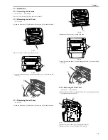
F-3-144
3.1.12.10 Removing the Power Supply Shield Plate
0011-6306
/ / FAX-L390 / / / FAX-L380S
1) Remove the five screws [1] to remove the power supply shield plate [2].
F-3-145
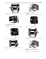
3.1.12.11 Removing the Paper Delivery Sensor
0011-6307
/ / FAX-L390 / / / FAX-L380S
1) Remove the connector [1] on the DCNT board and take the cable off the
cable guide. (The external cover is omitted from the illustration.)
2) Remove the screw [2] and remove the paper delivery sensor [3].
F-3-146
3.1.13 Paper Full Sensor
3.1.13.1 Removing the Cassette
0011-4756
/ / FAX-L390 / / / FAX-L380S
1) Remove the cassette by holding the cassette handle.
3.1.13.2 Removing the Right Cover
0011-4757
/ / FAX-L380S
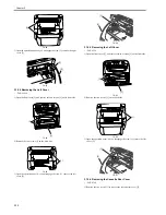
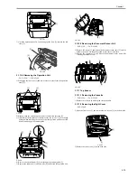
1) Open the front cover [1], and remove the two screws [2] on the front side.
F-3-147
2) Remove the two screws [1] on the back side.
F-3-148
3) Open the operation panel. As you disengage the claw [1], remove the right
cover [2].
F-3-149
3.1.13.3 Removing the Right Cover
0011-6313
/ / FAX-L390
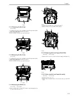
1) Open the front cover [1], and remove the two screws [2] on the front side.
F-3-150
2) Remove the two screws [1] on the back side.
[1]
[3]
[2]
[3]
[3]
[4]
[1]
[1]
[2]
[3]
[1]
[2]
[2]
[1]
[1]
[1]
[2]
[2]
[1]
Содержание FAX-L380S Series
Страница 1: ...Jan 19 2006 Service Manual FAX L380S Series ...
Страница 2: ......
Страница 6: ......
Страница 14: ...Contents ...
Страница 15: ...Chapter 1 PRODUCT DESCRIPTION ...
Страница 16: ......
Страница 18: ......
Страница 30: ......
Страница 31: ...Chapter 2 TECHNICAL REFERENCE ...
Страница 32: ......
Страница 34: ......
Страница 44: ......
Страница 45: ...Chapter 3 DISASSEMBLY AND ASSEMBLY ...
Страница 46: ......
Страница 52: ......
Страница 111: ...Chapter 4 MAINTENANCE AND INSPECTION ...
Страница 112: ......
Страница 114: ......
Страница 127: ...Chapter 5 TROUBLESHOOTING ...
Страница 128: ......
Страница 167: ...Chapter 6 APPENDIX ...
Страница 168: ......
Страница 170: ......
Страница 175: ...Jan 19 2006 ...
Страница 176: ......

