2. Installation Manual
- 2 -
2
2
P
P
r
r
o
o
d
d
u
u
c
c
t
t
C
C
o
o
n
n
f
f
i
i
g
g
u
u
r
r
a
a
t
t
i
i
o
o
n
n
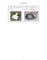
2.1 Product
Configuration
List
No. Item
Name Qty
Remarks
1
CXDI-50G/50C Imaging Unit
1
With Sensor cable (3/7m)
2
Power Box
1
100 - 120/230V
3
X-ray I/F cable
1
20m
4 Remote
switch
1 20m
5
Cable clump
1
For fixing the sensor cable
6
Screw (M4 x 6 mm) XB1-1400-603
1
For fixing the cable clump
7
Sensor Information File (FD)
1
8
Power supply cable (with AC plug)
1
3m (100/120/230V)
9
Attached documents for medical
-
(100V)
10
Certifications
(warranty registration, inspection
compliance, operation manual)
- (100V)
11
Inspection compliance, operation manual
-
(120/230V)
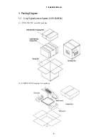
12 Packaging
-
LAN cable for connecting Control PC / Power Box and Network switch (Switching HUB) for
connecting the multiple Imaging Units shall be procured at each sales company.
- LAN cable (Over category 5)\
When Control PC and Power Box are connected directly, Cross type is used, but when they are
connected via Network switch, Straight type is used. However, this is not applied when
Network switch has AUTO-MDI/MDI-X function*.
- Network switch (Switching HUB)
Sales companies adopt Network switch (Switching HUB) after conducting the test and the
operation check for Switching HUB that meets the general standard.
* AUTO-MDI/MDI-X :
One of the functions of Network switch (Switching HUB) and Broadband-router.
They can detect Communication port of other side automatically and connect in proper procedure.
MDI: Network-card, etc.
MDI-X: Network switch (Switching HUB) and Broadband-router, etc.
Since AUTO-MDI/AUTO-MDI-X functions can detect automatically in proper procedure, they do not
require consideration to types of LAN cable (Straight of Cross cable).
Содержание CXDI-50C
Страница 15: ......
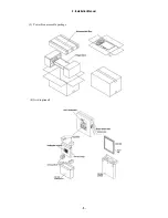
Страница 23: ...2 Installation Manual 6 3 Power Box assemble package 4 Grid optional ...
Страница 35: ...2 Installation Manual 18 When normal imaging When timeout due to RX_REQ not negating ...
Страница 63: ...2 Installation Manual 46 Fig 3 Input parameters ...
Страница 115: ...2 Installation Manual 98 2 Power Box Unit mm Mass 4 2Kg ...
Страница 116: ...2 Installation Manual 99 3 Remote Switch Unit mm Mass 0 5Kg 4 Grid Optional 508 27 452 Unit mm Mass 0 9Kg Frame ...
Страница 118: ......
Страница 138: ...4 Repair Guide 3 Do not touch the tabs when replacing the sensor cable Tabs in Enlarged View Sensor Cable ...
Страница 163: ......
Страница 167: ...CXDI SYSTEM 1 2 Rev 04 Key No 5 Key No 6 Key No 7 Key No 8 Key No 9 Canon Inc ...
Страница 186: ......
Страница 188: ......
Страница 189: ...Content 1 Gathering Information about Problems 1 2 How to back up and recover the system 3 ...


