5
5
5-28
5-28
Adjustment > Adjustment at Time of Parts Replacement > Adjusting Alignment Plate Position > Procedure
Adjustment > Adjustment at Time of Parts Replacement > Adjusting Alignment Plate Position > Procedure
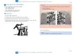
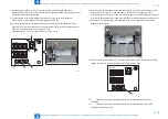
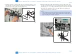
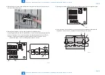
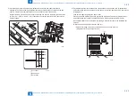
3) Place A4 paper [1] on the intermediate process tray. (Be sure to push in the paper to the
rear side of the process tray)
[1]
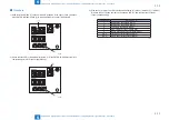
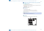
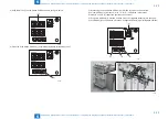
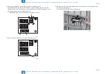
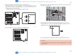
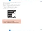
4) Pressing switch SW383 [1] or SW384 [2] determines adjustment level.
By pressing SW383 once, the LED [3] indicates "-1" and the front alignment plate [4] shifts
to the front by approx. 0.2mm. In the same way, by pressing SW384 once, the LED [3]
indicates "+1" and the front alignment plate [4] shifts to the rear by approx. 0.2mm.
• Adjustment range: +10 to -10 (shifting amount per unit: 0.2mm)
SW382
SW381
SW383
(-)
(+)
ENTER
SW384 SW385
DSP381
[1]
[2]
[3]
[4]
F-5-60
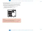
F-5-61
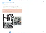
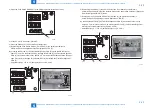
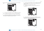
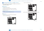
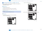
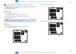
5) Pressing push switch SW385 [1] determines shifting amount of the front alignment plate.
SW382
SW381
SW383
(-)
(+)
ENTER
SW384 SW385
DSP381
[1]
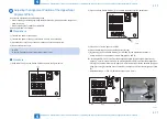
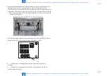
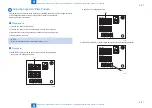
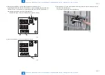
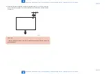
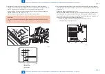
6) Check that there is no gap between the paper's edge and the alignment plate after the
adjustment. If there is a gap, go through the procedure again from step 4).
[2]
[1]
F-5-62
F-5-63
Содержание Booklet Finisher-D1
Страница 12: ... Notes Before Servicing Points to Note at Cleaning Safety Precautions ...
Страница 14: ...1 1 Product Outline Product Outline Product Specifications Names of Parts ...
Страница 60: ...3 3 Periodic Servicing Periodic Servicing User Maintenance Maintenance and Inspection ...
Страница 177: ...5 5 Adjustment Adjustment Basic Adjustment Adjustment at Time of Parts Replacement Auxiliary Adjustment ...
Страница 315: ...6 6 Troubleshooting Troubleshooting Upgrading ...
Страница 357: ... Service Tools Solvents and Oils List of Signals General Circuit Diagram Appendix ...

