Section 8. Operation
Terminal configured for control are inferred if parameter 5 of the
ModbusSlave()
instruction is set to 0. Coils are assigned to Modbus
registers
00001
to
09999
.
Term. digital registers 10001 to 19999
Hold values resulting from a digital measurement. Digital registers in the
Modbus domain are read-only. In the Campbell Scientific domain, the
leading digit in Modbus registers is ignored, and so are assigned together to a
single
Dim-
or
Public-
variable array (read / write).
Term. input registers 30001 to 39999
Hold values resulting from an analog measurement. Input registers in the
Modbus domain are read-only. In the Campbell Scientific domain, the
leading digit in Modbus registers is ignored, and so are assigned together to a
single
Dim
- or
Public
- variable array (read / write).
Term. holding registers 40001 to 49999
Hold values resulting from a programming action. Holding registers in the
Modbus domain are read / write. In the Campbell Scientific domain, the
leading digit in Modbus registers is ignored, and so are assigned together to a
single
Dim
or
Public
variable array (read / write).
Term. RTU / PLC
Remote Telemetry Units (RTUs) and Programmable Logic Controllers
(PLCs) were at one time used in exclusive applications. As technology
increases, however, the distinction between RTUs and PLCs becomes more
blurred. A CR1000 fits both RTU and PLC definitions.
8.6.2.2 Programming for Modbus
8.6.2.2.1 Declarations (Modbus Programming)
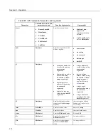
Table
CRBasic Ports, Flags, Variables, and Modbus Registers
(p. 413)
shows the
linkage between terminals configured for control, flags and Boolean variables and
Modbus registers. Modbus does not distinguish between terminals configured for
control, flags, or Boolean variables. By declaring only terminals configured for
control, or flags, or Boolean variables, the declared feature is addressed by
default. A typical CRBasic program for a Modbus application will declare
variables and ports, or variables and flags, or variables and Boolean variables.
413
Содержание CR1000
Страница 2: ......
Страница 4: ......
Страница 6: ......
Страница 32: ......
Страница 36: ......
Страница 38: ......
Страница 40: ......
Страница 60: ...Section 4 System Quickstart Figure 16 PC200W View Line Graph 60 ...
Страница 96: ......
Страница 98: ...98 ...
Страница 302: ......
Страница 350: ...Section 8 Operation Figure 91 Pulse Sensor Output Signal Types Figure 92 Switch Closure Pulse Sensor 350 ...
Страница 453: ...Section 8 Operation Figure 115 Using the Keyboard Display 453 ...
Страница 454: ...Section 8 Operation 8 8 1 Data Display Figure 116 Displaying Data with the Keyboard Display 454 ...
Страница 456: ...Section 8 Operation Figure 118 Real Time Custom 456 ...
Страница 457: ...Section 8 Operation 8 8 1 3 Final Memory Tables Figure 119 Final Memory Tables 457 ...
Страница 458: ...Section 8 Operation 8 8 2 Run Stop Program Figure 120 Run Stop Program 458 ...
Страница 460: ...Section 8 Operation Figure 122 File Edit 460 ...
Страница 461: ...Section 8 Operation 8 8 4 PCCard Memory Card Display Figure 123 PCCard CF Card Display 461 ...
Страница 478: ......
Страница 506: ......
Страница 536: ......
Страница 636: ......
Страница 642: ......
Страница 644: ......
Страница 676: ......
Страница 677: ......


