10
VI Air for Ventilation
Warning
OuTDOOr COMbusTiOn air MusT bE PiPED TO THE air inTaKE. nEVEr PiPE
COMbusTiOn air FrOM arEas COnTaining COnTaMinaTEs suCH as sWiMMing
POOls anD launDrY rOOM EXHausT VEnTs. COnTaMinaTED COMbusTiOn air Will
DaMagE THE bOilEr anD MaY CausE PrOPErTY DaMagE, PErsOnal inJurY Or
lOss OF liFE.
Air for combustion must always be obtained directly from outdoors, however sufficient air for ventilation must
still be provided in the boiler room. Air for ventilation is required to keep various boiler components from overheating
and is
always obtained from indoors. To ensure an adequate ventilation air supply, perform the following steps:
Step 1: Determine whether the boiler is to be installed in a confined space - A confined space is defined by the National
Fuel Gas Code as having a volume less than 50 cubic feet per 1000 BTU/hr input of all appliances installed in that
space. To determine whether the boiler room is a confined space:
• Total the input of all appliances in the boiler room in thousands of BTU/hr. Round the result to the next highest
1000 BTU/hr.
• Find the volume of the room in cubic feet. The volume of the room in cubic feet is:
Length (ft) x width (ft) x ceiling height (ft)
In calculating the volume of the boiler room, consider the volume of adjoining spaces only if no doors are
installed between them. If doors are installed between the boiler room and an adjoining space, do not consider
the volume of the adjoining space, even if the door is normally left open.
• Divide the volume of the boiler room by the input in thousands of BTU/hr. If the result is less than 50, the boiler
room is a confined space.
Example:
A FCM120 and a water heater are to be installed in a room measuring 6 ft – 3 in x 7 ft with an 8 ft ceiling. The
water heater has an input of 30000 BTU/hr:
Total input in thousands of BTU/hr = (120000 BTU/hr + 30000 BTU/hr) / 1000 = 150 MBTU/hr
Volume of room = 6.25 ft x 7 ft x 8 ft = 350 ft
3
350/150 = 2.33. Since 2.33 is less than 50, the boiler room is a confined space.
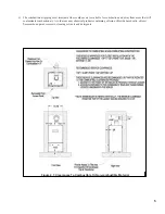
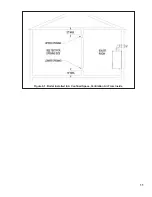
Step 2a: If the boiler is to be placed in a confined space, provide two openings into the boiler room, one near the floor and
one near the ceiling. The top edge of the upper opening must be within 12” of the ceiling and the bottom edge of
the lower opening must be within 12” of the floor (Figure 6.1). The minimum opening dimension is 3 inches.
• If the FCM boiler is the only gas-burning appliance in the boiler room, these openings must each have a
minimum free area of 100 square inches.
• If other gas-burning appliances are in the boiler room, size the openings in accordance with the appliance
manufacturer’s instructions or the National Fuel Gas Code. Minimum opening free area is 100 square inches
even if opening requirements for other appliances are less.
• If the total volume of both the boiler room and the room to which the openings connect is less than 50 cubic
feet per 1000 BTU/hr of total appliance input, install a pair of identical openings into a third room. Connect
additional rooms with openings until the total volume of all rooms is at least 50 cubic feet per 1000 BTU/hr of
input.
• The “free area” of an opening takes into account the blocking effect of mesh, grills, and louvers. Where screens
are used, they must be no finer than ¼” (4 x 4) mesh.
Step 2b: If the boiler is to be placed in an unconfined space the natural infiltration into the boiler room will provide
adequate air for ventilation without additional openings into boiler room.
Содержание FREEDOM
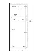
Страница 8: ...8 Figure 1 Wall Mounting Hole locations ...
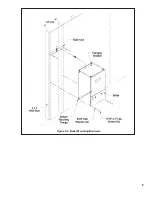
Страница 9: ...9 Figure 5 2 Boiler Mounting Hardware ...
Страница 11: ...11 Figure 6 1 Boiler Installed In A Confined Space Ventilation Air From Inside ...
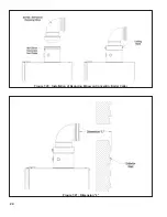
Страница 24: ...24 Figure 7 20 Installation of Reducing Elbow on Concentric Boiler Collar Figure 7 21 Dimension L ...
Страница 34: ...34 Figure 7 35b Cutting Vertical Terminal Figure 7 35c Completing Vertical Terminal Installation ...
Страница 42: ...42 FIGURE 7 51 CONDENSATE PIPING ARRANGEMENT ...
Страница 55: ...55 Figure 10 1 Wiring Connections Diagram ...
Страница 56: ...56 Figure 10 2 Ladder Diagram ...
Страница 57: ...57 Figure 10 3 Wiring of Isolation Relay for Control of Two Heating Circulators ...
Страница 60: ...60 FCM Series Lighting and Operating Instructions ...
Страница 66: ...66 FIGURE 12 2 BASIC MENU TREE ...
Страница 75: ...75 ...
Страница 77: ...77 ...
Страница 79: ...79 ...
Страница 80: ...80 ...
Страница 81: ...81 ...
Страница 83: ...83 150 151 152 153 154 155 ...
Страница 84: ...84 156 157 158 159 160 161 ...
Страница 85: ...85 162 ...


