27
D. Assembly of U.S. Boiler 80/125mm Concentric Venting
(IMPORTANT - See Section C for 60/100mm Concentric Vent Assembly)
Warning
Failure to follow the instructions could result in flue gas leakage into the combustion air or indoor
air, resulting in unsafe or unreliable operation
• Do not lubricate concentric gaskets with anything other than water.
• Do not attempt to cut any piping except as permitted in this section. When cutting these
sections, make sure all cuts are square and allow for proper insertion.
• Do not attempt to try to mix this concentric pipe with other venting systems.
1) The 60/100mm terminal section and concentric reducing elbow supplied with the boiler are not used in 80/125mm vent
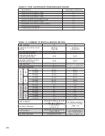
systems. The components listed in Table 7.4b are required for 80/125mm installations are not supplied with the boiler.
Before starting assembly of an 80/125mm vent system, make sure that the planned installation is in accordance with
the "Vent System Design" section of this manual and that all required 80/125mm vent components are on hand. These
components are available through U.S. Boiler distributors.
2) Cutting Straight Pipe - The following straight pipe sections may be cut:
Part No.
Description
101163-01
19-1/2" Straight
101162-01
39" Straight
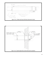
These sections have a plain male end (without beads - see Figure 7.30a). They are always cut from the male end.
Sections not shown on the above list may not be cut. These sections have beads on the male end (Figure 7.30b).
Figure 7.30a: Cuttable straight section
Figure 7.30b: non-Cuttable straight section
Содержание FREEDOM
Страница 8: ...8 Figure 1 Wall Mounting Hole locations ...
Страница 9: ...9 Figure 5 2 Boiler Mounting Hardware ...
Страница 11: ...11 Figure 6 1 Boiler Installed In A Confined Space Ventilation Air From Inside ...
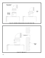
Страница 24: ...24 Figure 7 20 Installation of Reducing Elbow on Concentric Boiler Collar Figure 7 21 Dimension L ...
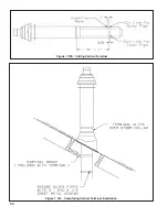
Страница 34: ...34 Figure 7 35b Cutting Vertical Terminal Figure 7 35c Completing Vertical Terminal Installation ...
Страница 42: ...42 FIGURE 7 51 CONDENSATE PIPING ARRANGEMENT ...
Страница 55: ...55 Figure 10 1 Wiring Connections Diagram ...
Страница 56: ...56 Figure 10 2 Ladder Diagram ...
Страница 57: ...57 Figure 10 3 Wiring of Isolation Relay for Control of Two Heating Circulators ...
Страница 60: ...60 FCM Series Lighting and Operating Instructions ...
Страница 66: ...66 FIGURE 12 2 BASIC MENU TREE ...
Страница 75: ...75 ...
Страница 77: ...77 ...
Страница 79: ...79 ...
Страница 80: ...80 ...
Страница 81: ...81 ...
Страница 83: ...83 150 151 152 153 154 155 ...
Страница 84: ...84 156 157 158 159 160 161 ...
Страница 85: ...85 162 ...

