


32
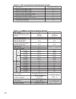
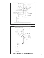
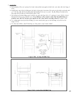
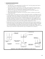
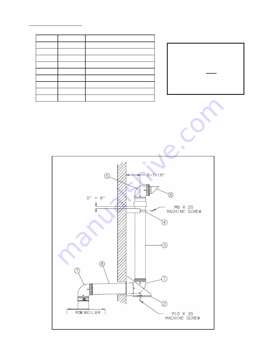
5) Snorkel Terminal Installation - The Snorkel Kit (P/N 101544-01) consists of the following (Also see Figure 7.34):
Key No.
Part No.
Description
1
101620-01
Support Elbow
2
101621-01
Lower Wall Bracket
3
101622-01
Air Intake Section
4
101623-01
Wall Bracket
5
101624-01
Terminal Elbow
6
101625-01
Exhaust Terminal
7
101490-01
Standard Elbow
8
101626-01
Wall Penetration Section
*
101627-01
Outer Joint Gasket (2 provided)
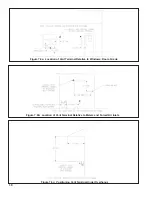
a) Cut a 6” diameter hole through the exterior wall at the planned exit point of the vent. A minimum of 4” is needed
between the center line of this hole and grade to install the lower wall bracket.
b) Before mounting the lower wall bracket, loosen the M10 x 35 screw on this bracket. Adjust this bolt forward or
backward so that its center is 6-7/16” from the wall (Figure 7.34) and tighten.
c) Center the Lower Wall Bracket on the hole in the wall and mark the location of the four mounting screws on the wall.
5/16” mounting screws (not supplied) are recommended for mounting this bracket. Drill mounting holes and mount
the bracket.
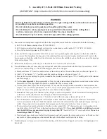
iMPOrTanT
The Terminal Elbow and Wall
Penetration Section included in
the snorkel kit have gaskets in the
female end of the outer pipe. These
gaskets prevent infi ltration of rain
water into the air intake section.
Do not interchange with similar
components shown in Table 7.4b.
Figure 7.34: Installation of Snorkel Terminal
Содержание FREEDOM
Страница 8: ...8 Figure 1 Wall Mounting Hole locations ...
Страница 9: ...9 Figure 5 2 Boiler Mounting Hardware ...
Страница 11: ...11 Figure 6 1 Boiler Installed In A Confined Space Ventilation Air From Inside ...
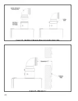
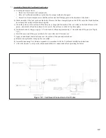
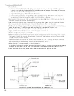
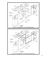
Страница 24: ...24 Figure 7 20 Installation of Reducing Elbow on Concentric Boiler Collar Figure 7 21 Dimension L ...
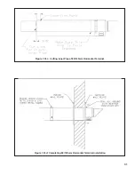
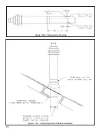
Страница 34: ...34 Figure 7 35b Cutting Vertical Terminal Figure 7 35c Completing Vertical Terminal Installation ...
Страница 42: ...42 FIGURE 7 51 CONDENSATE PIPING ARRANGEMENT ...
Страница 55: ...55 Figure 10 1 Wiring Connections Diagram ...
Страница 56: ...56 Figure 10 2 Ladder Diagram ...
Страница 57: ...57 Figure 10 3 Wiring of Isolation Relay for Control of Two Heating Circulators ...
Страница 60: ...60 FCM Series Lighting and Operating Instructions ...
Страница 66: ...66 FIGURE 12 2 BASIC MENU TREE ...
Страница 75: ...75 ...
Страница 77: ...77 ...
Страница 79: ...79 ...
Страница 80: ...80 ...
Страница 81: ...81 ...
Страница 83: ...83 150 151 152 153 154 155 ...
Страница 84: ...84 156 157 158 159 160 161 ...
Страница 85: ...85 162 ...


