78
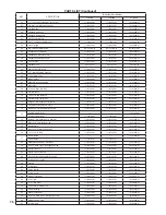
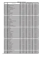
KEY
DESCRIPTION
(Quantity) Part Number
FCM070
FCM090
FCM120
46
½" x 11" Yellow Coated CSST, Nut by Nut
(1) 100396-01
(1) 100396-01
(1) 100396-01
47
5/8" OD x 1/2" MPT CSST Adaptor
(2) 100397-01
(2) 100397-01
(2) 100397-01
48
1/2" Blk Elbow
(1) 100539-01
(1) 100539-01
(1) 100539-01
49
Flanged Nipple Assy.
(1) 100398-01
(1) 100398-01
(1) 100398-01
50
Flanged Nipple Gasket
(1) 100399-01
(1) 100399-01
(1) 100399-01
51
Pipe Support Bracket
(1) 101010-01
(1) 101010-01
(1) 101010-01
52
3/4 x 1 x 3/4 Reducing Black Tee
(1) 101011-01
(1) 101011-01
(1) 101011-01
54
3/4 x 3" Nipple
(1) 100429-01
(1) 100429-01
(1) 100429-01
55
#10 x ½ Sheet Metal Screw
(36) 101012-01
(36) 101012-01
(36) 101012-01
56
Fluegas Sensor Grommet
(1) 101013-01
(1) 101013-01
(1) 101013-01
57
Fluegas NTC Mounting Plate
(1) 101014-01
(1) 101014-01
(1) 101014-01
59
Fluegas Temperature Sensor
(1) 101015-01
(1) 101015-01
(1) 101015-01
60
¾ x 3" Nipple
(1) 101016-01
(1) 101016-01
(1) 101016-01
61
¾ Black Cross
(1)101017-01
(1)101017-01
(1)101017-01
62
Hydrolevel #1100 LWCO
(1) 100456-01
(1) 100456-01
(1) 100456-01
63
¾ x 1 Black Reducing Coupling
(1) 101018-01
(1) 101018-01
(1) 101018-01
64
30 PSI Relief Valve
(1) 101019-01
(1) 101019-01
(1) 101019-01
65
Blower Gasket
(1) 100486-01
(1) 100486-01
(1) 100486-01
66
bLOWER, rg128/1300-3612
(1) 101020-01
(1) 101020-01
(1) 101020-01
67
M5 Locknut
(4) 101021-01
(4) 101021-01
(4) 101021-01
68
3 x 63mm Buna-N O-Ring
(1) 101022-01
(1) 101022-01
(1) 101022-01
69
Fan Inlet Block
(1) 101023-01
(1) 101023-01
(1) 101023-01
70
10-32 x 1/8 ID Hose Barb
(1) 101024-01
(1) 101024-01
(1) 101024-01
71
1/8 ID Silicone Tubing (12")
(1) 101025-01
(1) 101025-01
(1) 101025-01
72
Dungs Air Inlet Adaptor Part 2 (male)
(1) 101051-01
(1) 101051-01
(1) 101051-01
73
42.5mm Short Fan Adpator Plate
(1) 101052-01
(1) 101052-01
(1) 101052-01
74
M4 x 25mm Flat Head Machine Screw
(3) 101053-01
(3) 101053-01
(3) 101053-01
75
9mm Swirlplate (Red)
-----
-----
(1) 101054-01
5mm Swirlplate (Blue)
(1) 101166-01
(1) 101166-01
-----
76
Dungs Air Inlet Adaptor Part 1 (female)
(1) 101055-01
(1) 101055-01
(1) 101055-01
77
M4 x 10mm FH Machine Screw
(4) 101056-01
(4) 101056-01
(4) 101056-01
78
Injector Plate
(1) 101057-01
(1) 101057-01
(1) 101057-01
79
M4 x 25mm Positdrive Hd Screws
(3) 101058-01
(3) 101058-01
(3) 101058-01
80
1.5 x 17mm O-Ring
(1) 101059-01
(1) 101059-01
(1) 101059-01
81
7.0mm Orifice
-----
-----
(1) 101060-01
5.0mm Orifice
(1) 101167-01
(1) 101167-01
-----
82
GB-WND 055 Head On Gas Valve
(1) 101061-01
(1) 101061-01
(1) 101061-01
83
6-32 x ½ HWH Type F Self Tapping Screw
(6) 100462-01
(6) 100462-01
(6) 100462-01
84
Pressure Switch
(1) 101062-01
(1) 101062-01
(1) 101062-01
85
Pressure Switch Bracket
(1) 101063-01
(1) 101063-01
(1) 101063-01
86
M4 x 6mm Round Head Machine Screw
(2) 101064-01
(2) 101064-01
(2) 101064-01
87
Concentric Vent Collar
(1) 101026-01
(1) 101026-01
(1) 101026-01
88
Vent Kit
(1) 101065-01
(1) 101065-01
(1) 101065-01
89
Control Box
(1) 101027-01
(1) 101027-01
(1) 101027-01
90
Gauge Bracket
(1) 101028-01
(1) 101028-01
(1) 101028-01
91
Control Cover
(1) 101029-01
(1) 101029-01
(1) 101029-01
92
AT140 Transformer
(1) 100471-01
(1) 100471-01
(1) 100471-01
93
4 x 4 J-Box
(1) 100466-01
(1) 100466-01
(1) 100466-01
94
4 x 4 J-Box Cover
(1) 100467-01
(1) 100467-01
(1) 100467-01
95
10-32 x 3/8" Ground Screw
(1) 101030-01
(1) 101030-01
(1) 101030-01
96
Shutter Bushing
(2) 100424-01
(2) 100424-01
(2) 100424-01
97
AT250 Transformer
(1) 100474-01
(1) 100474-01
(1) 100474-01
98
4-40 x 1/2 HWH Type F Self Tapping screw
(8) 100463-01
(8) 100463-01
(8) 100463-01
99
MCBA (Programmed)
(1) 101066-01
(1) 101066-01
(1) 101066-01
101
Terminal Strip
(1) 100469-01
(1) 100469-01
(1) 100469-01
ParTs lisT (Continued)
Содержание FREEDOM
Страница 8: ...8 Figure 1 Wall Mounting Hole locations ...
Страница 9: ...9 Figure 5 2 Boiler Mounting Hardware ...
Страница 11: ...11 Figure 6 1 Boiler Installed In A Confined Space Ventilation Air From Inside ...
Страница 24: ...24 Figure 7 20 Installation of Reducing Elbow on Concentric Boiler Collar Figure 7 21 Dimension L ...
Страница 34: ...34 Figure 7 35b Cutting Vertical Terminal Figure 7 35c Completing Vertical Terminal Installation ...
Страница 42: ...42 FIGURE 7 51 CONDENSATE PIPING ARRANGEMENT ...
Страница 55: ...55 Figure 10 1 Wiring Connections Diagram ...
Страница 56: ...56 Figure 10 2 Ladder Diagram ...
Страница 57: ...57 Figure 10 3 Wiring of Isolation Relay for Control of Two Heating Circulators ...
Страница 60: ...60 FCM Series Lighting and Operating Instructions ...
Страница 66: ...66 FIGURE 12 2 BASIC MENU TREE ...
Страница 75: ...75 ...
Страница 77: ...77 ...
Страница 79: ...79 ...
Страница 80: ...80 ...
Страница 81: ...81 ...
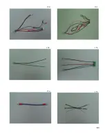
Страница 83: ...83 150 151 152 153 154 155 ...
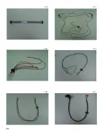
Страница 84: ...84 156 157 158 159 160 161 ...
Страница 85: ...85 162 ...

