CHAPTER 6 OPTIONS
6-17
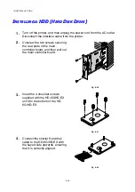
5.
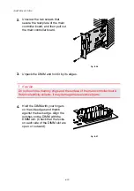
Fit the 4 HD-6G/HD-EX shoulder
screws into the 4 holes of the
main controller board, and then
secure the shoulder screws with
the screws provided from the rear
of the PCB.
Fig. 6-23
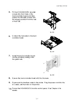
6.
Connect the flat cable to the main
controller board.
Fig. 6-24
7.
Install the main controller board
into the printer by sliding it into
the guide rails.
Fig. 6-25
8.
Secure the main controller board with the 2 screws.
9.
Reconnect the interface cable to the printer. Plug the power cord into the
AC outlet, and then turn on the printer.
10.
Format the HD-6G/HD-EX from the control panel. See Chapter 4 for
details.
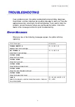
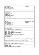
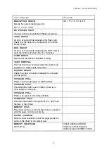
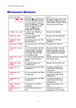
Содержание HL-3450CN Series
Страница 46: ...CHAPTER 2 DRIVER AND SOFTWARE 2 12 Graphics Tab 1 Set the print quality ...
Страница 116: ...CHPTER 5 MAINTENANCE C C CH H HA A AP P PT T TE E ER R R 5 5 5 M M MA A AI I IN N NT T TE E EN N NA A AN N NC C CE E E ...
Страница 156: ...CHPTER 6 OPTIONS C C CH H HA A AP P PT T TE E ER R R 6 6 6 O O OP P PT T TI I IO O ON N NS S S ...
Страница 207: ...APPENDIX A A AP P PP P PE E EN N ND D DI I IX X X ...
Страница 220: ...APPENDIX A 13 I I IB B BM M M M M MO O OD D DE E E PC 8 PC 8 D N PC 850 PC 852 PC 860 PC 863 PC 865 PC 8 Turkish ...

