Briggs & Stratton Twin Cylinder L-Head Скачать руководство пользователя страница 146

12

3

Check Rings

To check rings, first clean all carbon from the end of the
rings. Insert old rings one at a time, approximately one
inch down into the cylinder bore.

Check ring end gap with feeler gauge, Fig. 5. If ring end
gap is greater than shown in Table No. 1, the ring is
worn and should be replaced.

A worn ring will usually show scratches caused by
abrasives and/or have a shiny appearance. Also, the
top and bottom edges of the ring may be extremely
sharp. Never reuse worn piston rings.

ÇÇ

ÇÇ

ÇÇ

Fig. 5 – Checking Ring Gap

FEELER

GAUGE

RING

SEE CHART

Ring End Gap Rejection Size

ÁÁÁÁÁÁÁÁÁÁÁÁÁÁÁÁÁÁÁÁÁÁÁÁÁ

ÁÁÁÁÁÁÁÁÁÁÁÁÁÁÁÁÁÁÁÁÁÁÁÁÁ

ÁÁÁÁÁÁÁÁÁÁÁÁÁÁÁÁÁÁÁÁÁÁÁÁÁ

Basic Model

Series

ÁÁÁÁÁÁ

ÁÁÁÁÁÁ

ÁÁÁÁÁÁ

Compression

Ring

ÁÁÁÁÁ

ÁÁÁÁÁ

ÁÁÁÁÁ

Oil

Ring

ÁÁÁÁÁÁÁÁÁÁÁÁÁÁÁÁÁÁÁÁÁÁÁÁÁ

ÁÁÁÁÁÁÁÁÁÁÁÁÁÁÁÁÁÁÁÁÁÁÁÁÁ

ÁÁÁÁÁÁÁÁÁÁÁÁÁÁÁÁÁÁÁÁÁÁÁÁÁ

401400, 401700, 421400, 421700

ÁÁÁÁÁÁ

ÁÁÁÁÁÁ

ÁÁÁÁÁÁ

.035”

(.89 mm)

ÁÁÁÁÁ

ÁÁÁÁÁ

ÁÁÁÁÁ

.045”

(1.14 mm)

ÁÁÁÁÁÁÁÁÁÁÁÁÁÁÁÁÁÁÁÁÁÁÁÁÁ

ÁÁÁÁÁÁÁÁÁÁÁÁÁÁÁÁÁÁÁÁÁÁÁÁÁ

ÁÁÁÁÁÁÁÁÁÁÁÁÁÁÁÁÁÁÁÁÁÁÁÁÁ

400400, 400440, 400700, 400770, 402400, 402440, 402700, 402770, 404400,

404440, 404700, 404770, 422400, 422440, 422700, 422770, 462700

ÁÁÁÁÁÁ

ÁÁÁÁÁÁ

ÁÁÁÁÁÁ

.030”

(.76 mm)

ÁÁÁÁÁ

ÁÁÁÁÁ

ÁÁÁÁÁ

.035”

(.89 mm)

NOTE: If new piston rings are going to be installed in a cylinder that is within specification, the cylinder bore should

be reconditioned, using a rigid hone with finishing stones, to restore the proper cross hatch angle in the
cylinder bores. The proper cylinder cross hatch ensures proper lubrication and piston ring rotation. See
Section 11, Cylinder Finish (Cross Hatch), for procedure for applying cross hatch to cylinder bore.

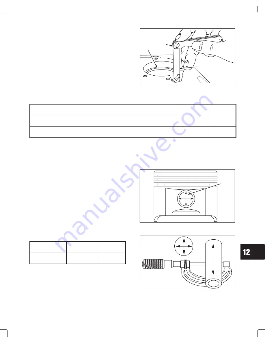
Check Piston Pin and Piston Pin Bore

If piston pin is worn .0005” (.01 mm) out of round or
below reject sizes shown in Table No. 2, it should be
replaced. If piston pin bore Fig. 6 is worn above reject
sizes, Table No. 2, oversize piston pin .005” (.13 mm) is
available. See Illustrated Parts List.

Fig. 6 – Checking Piston Pin Bore

PISTON

PIN

BORE

Piston Pin & Piston Pin Bore Reject Sizes

ÁÁÁÁÁÁÁ

ÁÁÁÁÁÁÁ

ÁÁÁÁÁÁÁ

Model Series

ÁÁÁÁÁÁ

ÁÁÁÁÁÁ

ÁÁÁÁÁÁ

Piston Pin

ÁÁÁÁÁ

ÁÁÁÁÁ

ÁÁÁÁÁ

Piston Pin

Bore

ÁÁÁÁÁÁÁ

ÁÁÁÁÁÁÁ

ÁÁÁÁÁÁÁ

ALL MODELS

ÁÁÁÁÁÁ

ÁÁÁÁÁÁ

ÁÁÁÁÁÁ

.799”

(20.29 mm)

ÁÁÁÁÁ

ÁÁÁÁÁ

ÁÁÁÁÁ

.802”

(20.37 mm)

Fig. 7 – Check Piston Pin

Содержание Twin Cylinder L-Head

Страница 1: ...For Briggs Stratton Discount Parts Call 606 678 9623 or 606 561 4983 www mymowerparts com ...

Страница 2: ...SSION Section 5 STARTERS Section 6 ALTERNATORS Section 7 LUBRICATION Section 8 ENGINE DISASSEMBLY Section 9 CYLINDERS BEARINGS Section 10 CRANKSHAFTS CAMSHAFTS Section 11 PISTONS RINGS RODS Section 12 ENGINE ASSEMBLY Section 13 TABLE OF CONTENTS For Section Reference See Pages VI through VIII MUFFLERS Section 14 I ...

Страница 3: ...25 0 Nm Cylinder Head 160 in lbs 18 0 Nm Fan Retainer 150 in lbs 17 0 Nm Flywheel 150 ft lbs 203 0 Nm Governor Control Bracket 35 in lbs 4 0 Nm Governor Lever Nut 100 in lbs 11 0 Nm Intake Manifold 90 in lbs 10 0 Nm Spark Plug 200 in lbs 22 0 Nm Starter Motor 160 in lbs 18 0 Nm Starter Motor Thru Bolts 50 in lbs 6 0 Nm Armature Air Gap Magnetron Ignition 008 012 0 20 0 30 mm Breaker Point Ignition...

Страница 4: ...34 95 mm PTO Journal 1 3776 1 3784 34 99 35 01 mm 1 376 34 95 mm Camshaft Journals 624 625 15 85 15 87 mm 623 15 82 mm Lobes Intake 14 16 18 20 HP 1 1525 1 1555 29 27 29 35 mm 1 150 29 20 mm Intake 12 5 HP 1 0575 1 0605 26 86 26 93 mm 1 055 26 80 mm Exhaust 12 5 14 16 18 HP 1 1225 1 1255 28 50 28 58 mm 1 120 28 45 mm Exhaust 20 HP 1 1525 1 1555 29 27 29 35 mm 1 150 29 20 mm Connecting Rod Crankpin...

Страница 5: ...0 7031 17 8594 7 32 0 2188 5 5562 23 32 0 7188 18 2562 15 64 0 2344 5 9531 47 64 0 7344 18 6531 1 4 0 2500 6 3500 3 4 0 7500 19 0500 17 64 0 2656 6 7469 49 64 0 7656 19 4469 9 32 0 2812 7 1438 25 32 0 7812 19 8438 19 64 0 2969 7 5406 51 64 0 7969 20 2406 5 16 0 3125 7 9375 13 16 0 8125 20 6375 21 64 0 3281 8 3344 53 64 0 8281 21 0344 11 32 0 3438 8 7312 27 32 0 8438 21 4312 23 64 0 3594 9 1281 55 ...

Страница 6: ...5 1495 24 152 23 154 5 32 1562 22 157 21 159 20 161 19 166 18 1695 11 64 1719 17 173 16 177 15 180 14 182 13 185 3 16 1875 12 189 11 191 10 1935 9 196 8 199 7 201 13 64 2031 6 204 5 2055 4 209 3 213 7 32 2188 2 221 1 228 A 234 15 64 2344 B 238 C 242 D 246 E 1 4 250 F 257 G 261 17 64 2656 H 266 I 272 J 277 K 281 9 32 2812 L 290 M 295 19 64 2969 N 302 5 16 3125 O 316 P 323 21 64 3281 Q 332 R 339 11 ...

Страница 7: ...ecking Battery 7 Bearings 10 Checking Installation Removal Repairing Breaker Points 2 Adjustment Installation Plunger Installation Removal Breather 8 Checking Installation Removal Camshaft Checking 11 Installation 13 Removal 9 Carburetor 3 Adjustment Anti Afterfire Systems Assembly Disassembly Basic Styles Inspection Intake Elbow Manifolds Removal Replace Float Needle Seat Replace Throttle Shaft B...

Страница 8: ...Engine Disassembly 9 Engine Identification System 1 Engine Specifications Preface Exhaust System See Mufflers 14 Flywheel 2 Installation Removal Also See Flywheel Identification 7 Fuel Filter 3 Fuel Recommendations 1 Fuel Pump 3 General Information 1 Governor 4 Adjustment Bushings Governed Idle Also See Governed Idle Adjustment 3 Ignition 2 Specifications Also See Check Ignition 1 Maintenance Sche...

Страница 9: ... Plug 1 Speed Control Adjustment 4 Splash Lube 8 Starters Electric 6B Assemble Disassemble Starter Assemble Disassemble Starter Drive Identification Replace Brushes Test Equipment Testing Troubleshooting Starter Rewind 6A Rope Installation Removal Spring Installation Removal Stop Switches 2 Testing Torque Specifications Preface Troubleshooting 1 Valves 6 Guides Installation Removal Refacing Seals ...

Страница 10: ...ling System 6 Replace Spark Plugs 6 Air Cleaner Maintenance 6 Service Dual Element Air Cleaner 6 To Service Pre Cleaner 6 To Service Cartridge 6 Remove Combustion Chamber Deposits 7 TROUBLESHOOTING 7 Systematic Check 7 Check Ignition With Electric Starter 8 Check Ignition Engine Running 8 Checking For Fouled Spark Plug 8 Check Carburetion 8 Check Compression 9 Cylinder Leakdown Test 9 Cylinder Bal...

Страница 11: ...ne speed before stopping DO NOT tamper with governor springs links or other parts to increase engine speed Run engine at speed set for equipment manufacturer DO NOT check for spark with spark plug removed Use an approved tester DO NOT run engine without blower housing or other safety shields removed when doing repairs DO NOT crank engine with spark plug removed If engine is flooded place throttle ...

Страница 12: ... 9 Vertical Shaft PulsaĆJet Carburetor Pneumatic or Mechanical Governor 0 Plain Bearing DU NonĆFlange Mount 1 Plain Bearing Flange Mounting 2 Sleeve Bearing Flange Mounting Splash Lube 3 Ball Bearing Flange Mounting Splash Lube 4 Ball Bearing Flange Mounting Pressure Lubrication on Horizontal Shaft 5 Plain Bearing Gear Reduction 6 to 1 CW Rotation Flange Mounting 6 Plain Bearing Gear Reduction 6 t...

Страница 13: ...on Oil has four purposes It cools cleans seals and lubricates During normal operation small particles of metal from the cylinder walls pistons bearings and combustion deposits will gradually contaminate the oil Dust particles from the air also contaminate the oil forming an abrasive mixture which can cause wear to all of the internal moving parts of the engine if the oil is not changed regularly F...

Страница 14: ...ange Oil Pressure Lube Engines The crankcase capacity of pressure lube twin cylinder engines is approximately 3 1 2 Pints 1 65 liters with filter 3 Pints 1 42 liters without filter IMPORTANT DO NOT OVERFILL Check and main tain oil level regularly Change oil after first five 5 hours of operation NOTE When checking oil level dipstick must be screwed all the way in for accurate readings Thereafter ch...

Страница 15: ... cleaner will be drawn into the engine These particles are highly abrasive and will cause the piston rings and cylinder bore to wear quickly As the rings and cylinder bore become worn these abrasive particles enter the crankcase and contaminate the oil forming an abra sive mixture which will cause wear on all of the internal moving parts The air cleaner on every engine brought in for a check up or...

Страница 16: ...nd cylinder head gasket surfaces NOTE Remove only the combustion chamber deposits It is not necessary to remove the discoloration marks on the piston valves and cylinder head These marks are normal and will not affect engine operation Remove the loose deposits from around the top ring land area using compressed air or a soft bristle brush WARNING TO PREVENT eye injury always wear eye protection wh...

Страница 17: ...ne if ignition is or is not at fault can be made by installing Tool 19368 ignition tester between the spark plug lead and each spark plug Fig 9 With the engine running a spark miss will be readily apparent If spark jumps gap at ignition tester regularly and engine misses check for a fouled spark plug Fig 9 Running Check IGNITION TESTER 19368 ATTACH TESTER TO EACH PLUG Checking For Fouled Spark Plu...

Страница 18: ... head 6 Warped valve stems 7 Worn bore and or rings 8 Broken connecting rods Cylinder Leakdown Test The cylinder leakdown tester Tool 19413 may be used to test the sealing capability of the compression components of each cylinder and quickly identify the problem component Cylinder Balance Test If the engine is hard starting runs rough misses or lacks power perform a cylinder balance test to determ...

Страница 19: ...pment powered rather than the engine itself Since many varied types of equipment are powered by Briggs Stratton engines it is not possible to list all of the various conditions that may exist Listed are the most common effects of equip ment problems and what to look for as the most common cause Hard Starting or Will Not Start 1 Loose belt a loose belt like a loose blade can cause a backlash effect...

Страница 20: ...FLYWHEEL 9 Remove Flywheel 9 Remove Flywheel Nut Pre Twin II Type Nos Under 1100 9 Remove Flywheel Nut Twin II Type Nos 1100 Above 9 Remove Flywheel All Models 9 Inspect Flywheel Key Keyways Flywheel and Crankshaft 10 Install Flywheel All Models 10 Torque Flywheel Nut Pre Twin II Models Type Nos Under 1100 10 Torque Flywheel Nut Twin II Models Type Nos 1100 Above 10 Flywheel Fan And Retainer Type ...

Страница 21: ...ained arma ture with transistor module b Earlier versions have a replaceable Magne tron transistor module mounted on the ignition armature The composite style Magnetron armature must be replaced as an assembly The Magnetron module can only be installed on armatures originally equipped with Magnetron module Fig 1 Magnetron Ignition COMPOSITE STYLE MODULE ARMATURE 2 Twin cylinder engines with type n...

Страница 22: ...netron Ignition Composite Style Armature 1 Remove spark plug leads and spark plugs 2 Remove rotating screen and blower housing 3 Remove armature screws and lift off armature Fig 4 a Disconnect stop switch wire at armature Fig 4 Remove Armature SPADE TERMINAL ARMATURE SCREWS GROUND WIRE Magnetron Ignition Armature With Magnetron Module 1 Remove spark plug leads and spark plugs 2 Remove rotating scr...

Страница 23: ...e NOTE Module can only be installed on armatures originally equipped with Magnetron The armature has a front side identified by the large rivet heads The module is installed with the retainer on the back side small rivet ends Fig 9 1 Assemble module to back side of armature a Make sure module retainer snaps over arma ture laminations Fig 9 Install Module BACK SIDE OF ARMATURE SHOWN SMALL RIVET END...

Страница 24: ...ires in illustrations for the type of armature being installed Fig 12 or Fig 13 Install Magnetron armature on engine as shown in Fig 12 Magnetron composite style armatures have identifi cations on the coil casing for correct assembly Fig 12 Install Armature Magnetron SHORTER WIRE TO CYLINDER 1 GROUND WIRE TERMINAL MODULE NOTE POSITION OF SPARK PLUG WIRES Install breaker point ignition armature as ...

Страница 25: ...aker points uses same opening to stop switch terminal Long spark plug lead is for 2 cylinder Route through same opening in back plate and under intake manifold to 2 spark plug Fig 15 Fig 15 Typical Wire Routing CYLINDER 2 1 BREATHER CYLINDER 1 BACK PLATE STOP SWITCH TERMINAL BREAKER POINTS Remove Breaker Points 1 Remove screw and breaker point cover 2 Remove condenser mounting screw 3 Loosen lock ...

Страница 26: ...tall ground wire condenser wire and armature primary wire to point terminal before installing points Fig 20 1 Turn locknut counterclockwise on adjusting screw until nut is at end of travel 2 Turn breaker point adjustment screw clockwise until locknut touches cylinder 3 Install condenser and mounting screw Fig 20 Install Breaker Points CONDENSER SHOULD BE STRAIGHT LOCATE WIRE AWAY FROM HOLE LOCATE ...

Страница 27: ...a piece of clean lintless paper between the points Rotate crankshaft until points close on paper Pivot paper on points Fig 22 then turn crankshaft until points open Repeat procedure until paper comes out clean Do not pull paper out while points are closed as dirt will pull off paper onto points Fig 22 Clean Points Install Breaker Point Cover Place Permatex or equivalent under armature prima ry wir...

Страница 28: ...H 19418 Remove Flywheel Nut Twin II Type Nos 1100 Above Remove debris guard or booster fan if so equipped Remove blower housing and rotating screen NOTE Do not remove fan retainer 1 Place flywheel holder Tool 19321 on fan retainer with lugs of flywheel holder engaging slots on the fan retainer Fig 25 2 Remove flywheel nut using 1 1 4 socket Fig 25 Remove Flywheel Nut 19321 FLYWHEEL HOLDER Remove F...

Страница 29: ...haft Torque Flywheel Nut Pre Twin II Models Type Nos Under 1100 1 Install flywheel washer and nut or clutch 2 Place flywheel strap wrench Tool 19433 around outer rim of flywheel 3 Torque flywheel nut or rewind clutch to 150 ft lbs 203 Nm Fig 28 4 Re install armature and adjust air gap Fig 28 Torque Flywheel Nut Pre Twin II TORQUE WRENCH STRAP WRENCH 19418 Torque Flywheel Nut Twin II Models Type No...

Страница 30: ...ss in flywheel with boss on back of fan Install fan retainer and screws Fig 30 Torque screws to 150 in lbs 17 0 Nm Fig 30 Installing Fan TORQUE SCREWS FAN RETAINER FAN BOSS RECESS STOP SWITCHES Various key and toggle stop switches have been provided by the Briggs Stratton Corporation to meet various equipment manufacturers needs Fig 31 Fig 31 Stop Switches SINGLE TERMINAL TOGGLE SINGLE TERMINAL RO...

Страница 31: ...urfaces must be free of paint rust or dirt Fig 32 Digital Multimeter Check Single Terminal Toggle Switch 1 Disconnect stop switch wire from spade terminal 2 Connect one meter lead to spade terminal and oth er lead to switch mounting surface or a good ground 3 With switch in OFF position there should be continuity 4 Move switch to ON position There should be no continuity Fig 33 Fig 33 Checking Ant...

Страница 32: ...buretor solenoid terminal L or S 3 With key in OFF position there should be no continuity Fig 36 4 With key in RUN and START position there should be continuity Fig 36 Checking Anti Afterfire Solenoid Circuit OFF START S OR L B Check Multiple Terminal Rotary Key Switch Stop Switch Circuit 1 Connect one meter lead to stop switch terminal M and other lead to a good ground If key switch is mounted to...

Страница 33: ...wire retainer and remove stop switch wire 2 Connect one meter lead to engine ground and other lead to stop switch wire retainer Fig 38 3 Move control lever to RUN position There should be no continuity 4 Move control lever to STOP position There should be continuity Fig 38 Fig 38 Checking Stationary Stop Switch ...

Страница 34: ...ent Style Type Nos 1100 And Above Engines Built After 98101500 10 Assemble Fuel Pump 12 INSTALL CARBURETOR 15 INSTALL AIR CLEANER ASSEMBLY 15 STATIC GOVERNOR ADJUSTMENT Before Running Engine 16 Initial Carburetor Adjustment All Engines Equipped With Adjustable Mixture Valves 16 Dynamic Governor Adjustment Type Nos 1100 And Above 16 Governed Idle Adjustment Type Nos 1100 And Above 17 Final Adjustme...

Страница 35: ... BODY CHOKE PLATE CHOKE SHAFT PLATE DIAPHRAGM SPRING DIAPHRAGM FLOAT PIN FLOAT NEEDLE GASKET FLOAT LOWER BODY FIXED JET GASKET PUMP BODY CUP THROTTLE PLATE THROTTLE SHAFT WASHER PLUG OR SOLENOID DIAPHRAGM SPACER SEAL ...

Страница 36: ...CLEANER MAINTENANCE PROCEDURES CARBURETOR STYLES Briggs Stratton Opposed Twin Cylinder engine models use three styles of two piece Flo Jet down draft carburetors All three styles incorporate an independent high speed fuel circuit and a separate idle speed fuel circuit An integral vacuum pulse type fuel pump allows remote fuel tank installations The fuel pump will prime at 18 46 0 cm maximum lift F...

Страница 37: ...USTMENT Previous Style Type Nos 1100 And Above Engines Built Before 98101500 The previous style carburetor may be identified by a welch plug located above the idle mixture valve or pilot jet Carburetors equipped with a pilot jet have no external adjustments other than idle speed The carburetor is equipped with fixed main jet or optional adjustable high speed mixture valve Fixed main jet carburetor...

Страница 38: ...ngeable with previous manifolds Twin II manifolds have no provision for mounting governor control brackets Fig 7 Current Style Intake Manifold CURRENT TWIN II MANIFOLD TYPE NOS 1100 ABOVE Engine Type Nos Under 1100 Two variations of early style manifolds were used the first was aluminum and was replaced by a one piece cast iron This style manifold had the governor control bracket mounted on the ma...

Страница 39: ...h governor lever and springs Fig 11 Fig 11 Remove Intake Manifold Carburetor GOVERNOR LEVER BOLT NUT 6 Remove carburetor mounting screws 7 Disconnect throttle link from governor lever Then from carburetor Fig 12 a Discard gaskets Fig 12 Disconnect Throttle Link THROTTLE LINK Vertical Crankshaft All Models 1 Remove air cleaner assembly 2 Remove fuel and vacuum lines from carburetor fuel pump body 3...

Страница 40: ... carburetor 2 Remove and discard all old gaskets seals and sealing material 3 Use commercial carburetor cleaning solvents such as Briggs Stratton Spray Cleaner Part 100041 or 100042 to clean carburetor parts and body 4 When cleaning non metallic parts plastic nylon Minlon etc do not leave in commercial carburetor cleaner more than 15 minutes NOTE Parts containing rubber such as seals O rings inlet...

Страница 41: ...ong 3 16 5 mm punch a Save plug 3 Install new bushings with flange side out Fig 17 Fig 17 Replace Nylon Bushing FLANGE SIDE OUT 4 Re install throttle shaft plug with 1 4 6 mm punch 5 Stake in three places around plug with 1 8 3 mm punch Fig 18 6 Apply sealant over plug to prevent air leaks Fig 18 Install Plug STAKE WITH PUNCH Replace Steel Throttle Shaft Bushings 1 Drive out throttle shaft plug wi...

Страница 42: ... Repeat procedure for other bushing Fig 21 Ream Bushing 19056 REAMER 8 Re install throttle shaft plug with 1 4 6 mm punch 9 Stake in three places around plug with 1 8 3 mm punch Fig 22 10 Apply sealant over plug to prevent air leaks STAKE WITH PUNCH Fig 22 Install Plug REPLACE FUEL INLET SEAT NOTE The inlet seat on current style carburetors engines built after 98101500 is NOT replaceable Remove In...

Страница 43: ...eat with 19135 driver Fig 25 IMPORTANT TO ENSURE proper float level be sure seat is flush with carburetor body Fig 25 Install Seat 19135 DRIVER PRESS IN FLUSH ASSEMBLE CARBURETOR Current Style Type Nos 1100 And Above Engines Built After 98101500 When assembling carburetor use new new seals and gaskets 1 Install choke shaft 2 Insert choke plate into choke shaft with offset slot toward choke lever s...

Страница 44: ...shaft and insert into carburetor body Fig 29 a Install throttle plate NOTE Use LOCTITE 222 on screw threads Fig 29 Install Throttle Shaft SEAL SPACER 6 Install idle jet 7 Install fixed main jet Fig 30 Fig 30 Install Jets IDLE JET FIXED MAIN JET 8 Assemble upper body to lower body Fig 31 9 Install fixed main jet plug or fuel solenoid a Torque to 100 in lbs 11 0 Nm Fig 31 Install Upper Body ...

Страница 45: ...ER DIAPHRAGM ASSEMBLE CARBURETOR Engines Built Before 98101500 When assembling carburetor use new new seals and gaskets 1 Install choke shaft Fig 34 2 Place choke plate on flat of choke shaft with notch facing away from fuel pump and dimple down NOTE Use LOCTITE 222 on screw threads Fig 34 Install Choke Shaft NOTCH OPPOSITE FUEL PUMP DIMPLE DOWN CHOKE SHAFT FUEL PUMP SIDE 3 Assemble body gasket to...

Страница 46: ...to gasket surface Fig 37 Check Float Height SAME FLOAT 8 Bend tang to adjust if necessary using needle nose pliers Fig 38 Fig 38 Adjust Float Height NEEDLE NOSE PLIERS FLOAT TANG 9 Assemble new seal to throttle shaft and insert into carburetor body Fig 39 a Install throttle plate with dimples up opposite idle port NOTE Use LOCTITE 222 on screw threads Fig 39 Install Throttle Shaft DIMPLES IDLE POR...

Страница 47: ...m Fig 40 Install Fixed Main Jet TORQUE 100 in lbs 11 0 Nm 12 Install upper body assembly Fig 41 Fig 41 Install Upper Body Assemble Fuel Pump 1 Place a small dab of grease on diaphragm valve spring bosses to hold springs in position a Assemble springs 2 Assemble fuel pump components as shown Fig 42 SCREWS DIAPHRAGM PUMP BODY CUP DIAPHRAGM PLATE GASKET DIAPHRAGM SPRING VALVE SPRINGS BASE SPRING BOSS...

Страница 48: ...ons Vertical Crankshaft Horizontal Crankshaft Before Code 91080000 Horizontal Crankshaft After Code 91080000 1 breather tube hole 2 breather tube holes Install new air cleaner gasket on carburetor making sure that holes in gasket align with holes in carburetor Install breather tube s in air cleaner base Fig 44 NOTE Breather tube installation will be easier if breather tube s are assembled to air c...

Страница 49: ...xture valve turn valve clockwise until it just seats DO NOT FORCE Turn valve counter clockwise 1 1 2 turns This setting will permit the engine to start Final adjustment will be made with the engine running Fig 46 NOTE Some early model carburetors are equipped with a fixed jet needle valve NO TAG Turn fixed jet needle in until it seats firmly Backing needle out will cause an excessively rich mixtur...

Страница 50: ... rich and lean Fig 49 Fig 49 Adjust Idle Mixture IDLE SPEED ADJUSTING SCREW THROTTLE LEVER IDLE MIXTURE VALVE 6 Hold throttle lever against idle speed screw adjust idle speed to 1000 RPM 7 Release throttle lever 8 With tang bending tool bend governed idle tang to obtain 1300 RPM Fig 50 Fig 50 Adjust Governed Idle INCREASE TANG BENDER DECREASE TANG Final Adjustment Type Nos 1100 And Above High Spee...

Страница 51: ...ainst idle speed screw adjust idle speed to 1000 RPM 6 Release throttle lever Fig 53 Adjust Idle Mixture IDLE MIXTURE VALVE THROTTLE LEVER IDLE SPEED ADJUSTING SCREW 7 Move equipment speed control lever until 1 8 3 mm rod can be inserted through the 2 holes in the governor control plate Fig 54 8 With tang bending tool bend governed idle tang to obtain 1300 RPM Fig 54 Fig 54 Adjust Governed Idle TO...

Страница 52: ...ust be in Weld mode ANTI AFTERFIRE SYSTEM Some carburetors are equipped with a fuel shut off solenoid controlled by the equipment ignition switch When the equipment switch is in the Off position the solenoid valve plunger closes stopping fuel flow through the fixed main jet Fig 57 When the switch is in the On and Start position the solenoid valve opens allowing normal fuel flow Fig 58 Solenoid is ...

Страница 53: ...oltage test solenoid Fig 60 Test Equipment Wiring EQUIPMENT WIRING HARNESS CONNECTOR Testing Solenoid 1 Remove solenoid from carburetor 2 Place either terminal of a 9 volt transistor battery on the solenoid connector and other terminal on body of solenoid Fig 61 3 Plunger should retract freely 4 When battery is removed plunger should return freely Replace solenoid if plunger sticks or doesn t move...

Страница 54: ...lines should have sharp bends or kinks Check gaskets and O ring in vacuum block for leaks Replace damaged or leaking gaskets or O ring Inspect Anti Afterfire System Electrical Check for loose or corroded ground wire connections loose or corroded connections at vacuum valve and equipment ignition switch Solenoid is operating prop erly if a click is heard when equipment ignition switch is turned ON ...

Страница 55: ......

Страница 56: ... Twin ll Type Nos Below 1100 6 Remove Governor Shaft Early Style 5 Replace Governor Shaft Bushing Twin II Type Nos 1100 Above 6 Install Governor Shaft Twin ll Type Nos 1100 Above 7 Replace Governor Shaft Bushing Pre Twin II Type Nos Below 1100 7 Install Governor Shaft Pre Twin II Type Nos Below 1100 7 Install Governor Shaft Early Style 8 Install Governor Gear 8 Install Crankcase Cover Or Sump 8 ST...

Страница 57: ...alled check engine top governed speed with an accurate tachometer The governed speed on Twin II engines can be varied by changing governor springs or hole location NO TAG NOTE If Top No Load adjustment exceeds 100 RPM the governor spring must be changed Fig 1 Governor Spring Twin II Type Nos 1100 Above 1 HOLE NORMAL GOVERNOR SPRING HOLE 2 HOLE FOR GENERATOR APPLICATION GOVERNOR SPRING ÏÏÏÏÏÏÏ ÏÏÏÏ...

Страница 58: ...e Control Wire Travel In order to make proper remote control adjustments the travel of the remote control wire must be not less than 1 3 8 35 mm with controls mounted in equipment Fig 3 Fig 4 Control Wire Travel 2 1 8 MINIMUM 54 mm 1 3 8 MINIMUM TRAVEL 35 mm CONTROL ADJUSTMENTS Remote Control Adjustment Twin II Type Nos 1100 Above Horizontal Crankshaft 1 Loosen control casing clamp at governor con...

Страница 59: ...Type Nos Below 1100 Vertical Crankshaft 1 Move speed control lever to full SLOW position 2 Loosen control casing clamp at governor control bracket or intake manifold 3 Move control casing and wire in direction shown by arrow Fig 8 NOTE Carburetor throttle must touch idle speed adjustment screw when control lever is in slowest position 4 Tighten casing clamp screw Fig 8 Remote Control Adjustment Pr...

Страница 60: ...hinge pins for wear and burrs 3 Check governor cup for wear and burrs Replace as required Fig 11 Governor Gear Assembly Typical COUNTER WEIGHTS CUP GEAR PIN Remove Governor Shaft NOTE On Twin II engines the intake manifold carburetor assembly and governor control must be removed before the governor shaft can be removed Plain Bearing Engines 1 Rotate crankshaft until timing mark on gear is at about...

Страница 61: ...ecessary Fig 15 Governor Shaft Assembly Pre Twin II E RING FOAM SEAL GOVERNOR SHAFT BUSHING E RING GOVERNOR SUPPORT BUSHING THRUST WASHER SUPPORT POST CYLINDER RIB ROTATE SHAFT UNTIL CRANK TOUCHES RIB Remove Governor Shaft Early Style 1 While pushing up on governor shaft remove E ring and thick washer Fig 16 2 Lower shaft into cylinder If governor shaft hits crankshaft rock crankshaft back and for...

Страница 62: ... RIB THRUST WASHER GOVERNOR SHAFT SUPPORT BUSHING GOVERNOR SHAFT GOVERNOR PADDLE Replace Governor Shaft Bushing Pre Twin II Type Nos Below 1100 1 Drive out worn bushing from crankcase side with a 3 8 9 5 mm rod 2 Install new bushing using Tool 19204 to press bushing in until it bottoms Fig 20 Fig 20 Replace Bushing TOOL 19204 BUSHING Install Governor Shaft Pre Twin II Type Nos Below 1100 1 Install...

Страница 63: ...INER GOVERNOR GEAR AND WEIGHTS THRUST WASHER Install Crankcase Cover Or Sump 1 Rotate crankshaft until 1 intake valve is wide open 2 Install crankcase cover or sump with new gasket 3 To engage governor gear horizontal or vertical crankshaft models and oil slinger vertical crank shaft models rock crankshaft back and forth 4 Torque cover or sump bolts to 225 in lbs 25 0 Nm Fig 24 3 4 5 6 7 1 2 Fig 2...

Страница 64: ...els NOTE Carburetor mixture adjustments must be made before adjusting governed idle and top no load RPM Assemble remote controls and check for proper adjustment The following tools are required when making governor adjustments Fig 27 1 Tachometer Tool 19200 or 19389 2 Tang bender Tool 19229 or 19352 Start and run engine for approximately 5 minutes to allow engine to warm up Fig 27 Governor Adjustm...

Страница 65: ... change governor spring Fig 30 Top No Load Adjustment Screw INCREASE DECREASE Fixed Speed Adjustable Generator Twin II Type Nos 1100 Above 1 Disconnect speed regulator knob from bracket and loosen knob to end of threads 2 Push adjustment rod in as far as it will go 3 While holding rod in bend governed idle tang to obtain 1300 RPM Fig 31 Fig 31 Adjust Governed Idle FIXED ADJUSTABLE ROD INCREASE DEC...

Страница 66: ...to obtain 1300 RPM 3 Remove 1 8 3 mm rod Engine RPM should not change If engine RPM changes check remote control adjust ment Fig 34 Adjust Governed Idle TANG BENDER TANG DECREASE 1 8 3 mm ROD 4 Refer to Service Engine Sales Manual Microfiche MS 6225 or the Service Sales Manual MS 4052 for Top No Load RPM by engine model and type number 5 Check governor spring hole position for proper location for ...

Страница 67: ...00 TO 4000 RPM 3700 TO 3800 RPM 3400 TO 3600 RPM 3200 TO 3300 RPM 2700 TO 3100 RPM 6 Move lever to obtain specified Top No Load RPM 7 Tighten lock screw and washer Fig 39 8 Bend tang until it touches speed control lever LOCKING SCREW WASHER BEND TANG Fig 39 Adjust Top No Load Fixed Speed Adjustable Pre Twin II Type Nos Below 1100 1 Turn speed regulator nut counterclockwise until a 1 8 3 mm rod can...

Страница 68: ...vernor spring With machine set in low speed position start engine and adjust speed regulator nut to obtain 1850 RPM No Load Fig 42 Fig 42 Adjust Low Speed SPEED REGULATOR NUT 3 Stop engine and reinstall governed idle spring Stop engine 4 Start engine and bend governed idle tang to obtain 1875 RPM No Load Fig 43 5 Stop engine 6 Reinstall main governor spring in 3 governor lever hole Fig 43 Fig 43 A...

Страница 69: ...ing nut to obtain 1850 RPM Top No Load RPM Fig 45 2 Stop engine Fig 45 Adjust Low Speed SPEED REGULATOR NUT 3 Reinstall governed idle spring and start engine 4 Bend governed idle tang to obtain 1875 RPM Top No Load RPM Fig 46 Fig 46 Adjust High Speed INCREASE ADJUSTING KNOB DECREASE INSTALL GOVERNOR SPRING IN 3 HOLE INCREASE ...

Страница 70: ...aming 5 Finish Reaming 6 Replace Brass or Sintered Iron Valve Guides Remove Bushing 6 Valve Guide Bushing Identification 7 Special Instructions 7 Install Bushing 7 Finish Reaming 7 REFACE VALVES AND SEATS 7 Inspect Valve Seats 8 Remove Valve Seat 9 Install Valve Seat 9 Valve Seat Inserts 9 Installing Part 21612 Exhaust Valve Seat Insert 10 CHECK AND ADJUST VALVE CLEARANCE 11 INSTALL VALVES 11 Inst...

Страница 71: ...n in Fig 1 Fig 1 Cylinder Number Location CYLINDER IDENTIFICATION NUMBER 2 1 42 2 42 1 CYLINDER HEAD REMOVAL 1 Disconnect spark plug wires and remove spark plugs Remove blower housing 2 Remove cylinder air guides and cylinder shields Fig 2 and Fig 3 Fig 2 Cylinder Ducting CYLINDER AIR GUIDES AIR GUIDE FRAME Fig 3 Non Ducted Engine CYLINDER HEAD COVER CYLINDER SHIELD ...

Страница 72: ...ntake manifold and carburetor Section 3 3 Remove air guide breather cover and breather s Fig 5 and Fig 6 4 Remove dipstick assembly on horizontal crank shaft models with one breather Fig 5 Removing Breather Vertical Crankshaft Engines BREATHER COVER AIR GUIDE BREATHER GASKETS NOTE Horizontal crankshaft twin cylinder engines manufactured after 91080000 have only one breather valve and breather tube...

Страница 73: ...all of valve tappet chamber and exhaust valve spring The other jaw goes below valve spring retainer 3 Tighten compressor until spring is fully compressed and remove split retainers 4 Remove exhaust valve from guide Then remove exhaust valve spring and compressor Fig 8 NOTE Exhaust valve springs are dyed RED DO NOT MIX Fig 8 Removing Retainers Exhaust SPLIT RETAINER TOOL 19063 Remove Intake Valve 1...

Страница 74: ...counter bore reamer 19231 into worn valve guide 2 Place new service bushing Part 231218 on pilot bushing next to reamer 3 Mark reamer level to 1 16 1 6 mm above top edge of service bushing Fig 11 Fig 11 Mark Reamer MARK PILOT BUSHING PILOT OF COUNTERBORE REAMER BUSHING REPLACEMENT 4 Lubricate reamer with Stanisol or kerosene 5 Turn reamer clockwise until mark on reamer is flush with top of guide b...

Страница 75: ...ushing with engine oil or kerosene 2 Using a tap wrench turn tap clockwise into valve guide bushing approximately 1 2 13 mm DO NOT turn tap more than 1 25 4 mm deep 3 Remove tap and clean chips from bushing threads Fig 15 METRIC TAP 19264 Fig 15 Thread Bushing 4 Thread Nut Tool 19239 up until it touches head of Puller Screw Tool 19238 5 Place Puller Washer Tool 19240 over valve seat keeping it cen...

Страница 76: ...s not require finish reaming however it is recommended to ensure that the entire guide is clean and free of foreign material 1 Finish ream guide with reamer 19233 and pilot guide 19234 Fig 20 a Lubricate reamer with Stanisol or kerosene 2 Ream clockwise through entire guide into valve tappet chamber Fig 20 3 Keep turning reamer clockwise when removing reamer from guide a Flush out all chips Fig 20...

Страница 77: ...n in Fig 21 a Use a 60 cutter to narrow seat from bottom and a 30 cutter to narrow seat from top Fig 23 Fig 23 Exhaust Valve Seat Dimensions 45 VALVE SEAT DIMENSIONS ÉÉÉ ÉÉÉ 60 CUTTER 30 CUTTER ÉÉÉ ÉÉÉ ÉÉÉ ÉÉÉ ÉÉÉ ÉÉÉ ÉÉÉ ÉÉÉ 1 16 3 64 0 8 mm 1 2 mm Inspect Valve Seats Check valve seat inserts for tightness If seat can be rotated or moved up and down check seat with 005 13 mm feeler gauge Fig 24 I...

Страница 78: ...Á ÁÁÁÁÁÁÁÁ ÁÁÁÁÁÁÁÁ Puller Nut ÁÁÁÁÁÁÁÁÁÁÁÁ ÁÁÁÁÁÁÁÁÁÁÁÁ 401400 Before Code No 80072812 ÁÁÁÁÁ ÁÁÁÁÁ 211661 ÁÁÁÁÁ ÁÁÁÁÁ 213316 21612 ÁÁÁÁÁÁÁÁ ÁÁÁÁÁÁÁÁ 19138 ÁÁÁÁÁÁÁÁ ÁÁÁÁÁÁÁÁ 19141 ALL ÁÁÁÁÁÁÁÁÁÁÁÁ ÁÁÁÁÁÁÁÁÁÁÁÁ ÁÁÁÁÁÁÁÁÁÁÁÁ 401400 After Code No 80072712 ÁÁÁÁÁ ÁÁÁÁÁ ÁÁÁÁÁ 261463 ÁÁÁÁÁ ÁÁÁÁÁ ÁÁÁÁÁ 213316 21612 ÁÁÁÁÁÁÁÁ ÁÁÁÁÁÁÁÁ ÁÁÁÁÁÁÁÁ 19138 ÁÁÁÁÁÁÁÁ ÁÁÁÁÁÁÁÁ ÁÁÁÁÁÁÁÁ INTAKE NONE EXHAUST 19141 ÁÁÁÁÁ...

Страница 79: ...to one side or it will cut oversize a Lubricate with Stanisol or kerosene 5 Remove all chips Fig 28 Counterboring for Valve Seat CUTTER STOP PILOT 19129 CUTTER SHANK 19131 CUTTER 6 Place drive pilot Tool 19127 in valve guide 7 Place 21612 insert on seat counterbore with radius down Use old insert as a spacer between new seat and insert driver Tool 19136 8 Drive seat insert in until it bottoms Fig ...

Страница 80: ...8 mm INSTALL VALVES Important Valve stems and valve guides must be free of foreign material and burrs or valve sticking may occur causing short valve life and burning Install Intake Valve and Seal 1 Coat valve stems with valve guide lubricant Tool 93963 and install in intake valve guide until stem just starts to enter valve tappet chamber Fig 31 NOTE Be sure valve guide lubricant Part 93963 is not...

Страница 81: ...he cylinder head loose Install long bolts around the exhaust valve area of the cylinder head torque sequence 1 3 7 Fig 34 1 Assemble cylinder heads with new head gasket and cylinder head screws in correct location 2 Apply anti seize lubricant 93963 to threads of head bolts DO NOT USE SEALER OF ANY KIND ON GASKETS 3 Torque head bolts in 40 in lbs 5 0 Nm incre ments in sequence shown to 160 in lbs 1...

Страница 82: ...gines is illustrated in Fig 1 Rewind starter assembly is held on blower housing with four 4 studs nuts and lock washers Fig 1 Rewind Starter STUD AND NUT BLOWER HOUSING REWIND STARTER ROPE HANDLE DISASSEMBLY Remove Spring 1 Pull rope handle and rope out part way and tie a temporary knot 2 Pull rope pin and rope out of handle and untie knot 3 Untie temporary knot and allow rope to rewind into rewin...

Страница 83: ...atchet spring ratchet spring adapter and pulley into rewind housing and bend tang down Fig 4 Tang bender Tool 19229 can be used to adjust tang gap Fig 4 Pulley must be fully depressed when measuring tang gap Fig 5 Lubricate Adapter GREASE RATCHET SPRING RATCHET SPRING ADAPTER NOTE If tang breaks use alternate unused tangs to hold pulley Wind Spring 1 Place a 3 4 19 0 mm square piece of stock into ...

Страница 84: ...f re using old rope burn pulley end of rope with a match Wipe with waste cloth using caution while it is still hot to prevent swelling and unraveling Fig 9 Tie Knot Fig 10 Rope Inserter WOOD HANDLE 1 16 1 6 mm DIA 6 152 mm 3 32 2 36 mm FLATTEN 1 8 3 17 mm NOTE Check parts list to be sure new rope is the correct diameter and length 4 Thread rope through rope eyelet in housing and out pulley hole Fi...

Страница 85: ...ed starter clutch Fig 12 Disassembling Sealed Clutch 1 Do not oil balls or ball cavity area in clutch housing 2 Place one drop of engine oil on end of crankshaft before replacing clutch assembly on crankshaft 3 Torque clutch to same specification as flywheel nut NOTE Clean ratchet by wiping with cloth only Fig 13 Sealed Clutch Assembly SEAL RATCHET CLUTCH HOUSING CLUTCH HOUSING 6 BALLS ...

Страница 86: ...Drive 5 Disassemble Starter Motor Drive C ring Style 5 Disassemble Starter Motor Drive Roll Pin Style 6 Inspect Starter Drive All 6 Assemble Starter Drive C ring Style 7 Assemble Starter Drive Roll Pin Style 7 Assemble Starter Drive Roll Pin Style With Plastic Cap 8 STARTER MOTOR 9 Disassemble Starter Motor 9 Replace Brushes 10 Inspect Armature Commutator 10 Inspect Brushes 10 ASSEMBLE STARTER MOT...

Страница 87: ...AL Fig 2 Vertical Crankshaft Engines STARTER MOTOR TYPICAL Starter Identification Briggs Stratton Twin Cylinder engines have used three styles of 12V starters Current style starters have a molded plastic stamped steel or aluminum brush end cap and long starter housing Fig 3 and Fig 4 Early style starters had a die cast brush end cap and short housing Fig 5 Fig 3 Current Style Starters 4 1 2 114 mm...

Страница 88: ... pinion or ring gear c Battery faulty or damaged d Incorrect rotation due to reversed motor polar ity all motors rotate counterclockwise viewed from pinion gear 4 Starter Motor Spins Will Not Stop a Defective starter switch TEST EQUIPMENT The following is a list of equipment recommended to test and repair starter motors Digital Multimeter The Digital Multimeter is available from your Briggs Stratt...

Страница 89: ...tor housing is hit deformed or dented NOTE A fully charged 12 volt battery is required Fig 10 Testing 12 Volt Starter Motor Digital Multimeter DC Shunt DIGITAL MULTIMETER STARTER SWITCH OPTIONAL BLACK TEST LEAD FROM METER RED TEST LEAD FROM METER BLACK MOUNT TACHOMETER APPROXIMATELY AS SHOWN ON HANDLE MOUNT HANDLE IN VISE AS SHOWN BRACKET FROM PAGE 4 ROTATE DIAL ON TACHOMETER WHILE STARTER IS RUNN...

Страница 90: ...and pinion gear for freedom of operation The pinion must move freely on the helix for correct starter operation If any sticking occurs this must be corrected Twin cylinder starters use three styles of starter pinion gear retainer mechanisms Fig 12 Fig 13 Fig 14 Fig 12 C ring Style ROLL PIN PLASTIC CAP Fig 13 Roll Pin Style Fig 14 Roll Pin Style With Plastic Cap Early Style Disassemble Starter Moto...

Страница 91: ...Place starter drive retainer on support block Fig 18 and drive out roll pin with a 5 32 4 mm pin punch to remove starter drive retainer 1 25 4 mm Fig 18 Disassemble Starter Drive Roll Pin Style 2 50 8 mm 2 5 16 58 7 mm 3 8 9 5 mm 5 127 mm 1 25 4 mm Inspect Starter Drive All The pinion gear should be inspected for damaged teeth Pinion gear must move freely on helix The parts may be washed in a solv...

Страница 92: ... end of C ring Fig 20 5 Press or drive C ring on until it snaps into groove in shaft Fig 20 Installing C ring C RING TOOL 19435 SLOT Assemble Starter Drive Roll Pin Style 1 Assemble starter clutch to starter shaft and rotate clutch until it drops into place 2 Install pinion gear with chamfered edge of pinion gear teeth away from motor Fig 21 3 Assemble thrust washer and clutch retainer assembly on...

Страница 93: ...ve NEW roll pin through retainer slot and hole in armature shaft Fig 22 Roll pin should be centered in armature shaft within 1 32 0 8 mm Fig 22 Assembling Starter Drive Roll Pin Style With Plastic Cap COVER CLUTCH RETAINER STARTER CLUTCH ROLL PIN SLOT UP RETURN SPRING CHAMFERED TEETH UP SPRING RETAINER CUP 5 To install plastic cap use a socket approximately the same diameter as the plastic cap for...

Страница 94: ... AND DRIVE ASSEMBLY DRIVE END CAP SPRING WASHER HOUSING ARMATURE END CAP SPRING C RING THRUST WASHER SPRING WASHER THRUST WASHER 1 Remove starter drive 2 Remove thru bolts Drive end head assembly can now be removed 3 Inspect bushing for wear or damage Replace if worn or damaged 4 Hold the armature and commutator end cap against a work surface while sliding housing off the armature Fig 25 NOTE This...

Страница 95: ...sure should be strong enough to ensure good brush contact with armature Check to be sure brushes are not sticking in their holders Minimum brush dimension is 1 4 6 mm Fig 27 Fig 26 Cleaning Commutator PIECE OF BROKEN HACKSAW BLADE Fig 27 Checking Brushes NORMAL LENGTH NEW 1 4 6 mm OR LESS REPLACE Replace Brushes Three different style brush end caps are used Refer to Fig 28 Fig 29 and Fig 30 for co...

Страница 96: ... Spring Type On end caps with compression type springs insert brushes in their proper holders Fig 32 and Fig 33 A brush retainer should be used to hold brushes clear of armature commutator Fig 32 Compression Spring Type Brush Holders 3 8 9 5 mm 5 8 15 9 mm 1 25 4 mm 1 8 3 2 mm 1 4 6 4 mm 1 4 6 4 mm 1 8 3 2 mm 1 2 12 7 mm 4 Brush retainers can be made from scrap pieces of rewind starter springs as ...

Страница 97: ...h on starter housing which faces brush end cap 7 While pushing down on armature and brush end cap slide starter housing over armature 8 Align seam on housing with boss on brush end cap Fig 37 DO NOT damage magnets in starter housing Fig 37 Assemble Starter SEAM BOSS NOTCH Install Drive End Cap 1 Assemble spring washer and thrust washer to armature shaft Fig 38 2 Install drive end cap Torque screws...

Страница 98: ...ecommended procedure WARNING WEAR EYE protection when servicing the battery Avoid skin contact If contact does occur flush with cold water and consult a physician immediately CAUTION BEFORE SERVICING battery disconnect negative battery cable first then positive cable Arcing which could cause a fire can occur when cables are improperly disconnected WARNING BATTERIES PRODUCE hydro gen an explosive g...

Страница 99: ...READINGS ARE BELOW 1 225 OR IF CELLS VARY BY MORE THAN 50 Testing Battery Use Digital Multimeter Tool 19357 or 19390 Set meter to read DC Volts Attach RED meter test clip to positive battery terminal Attach BLACK meter test lead to negative battery terminal With ignition switch OFF press starter button If ignition switch and starter switch are the same switch disconnect wires from spark plugs and ...

Страница 100: ...Charging Circuit Red Wire 9 Lighting Circuit White Wire 9 5 9 AMP REGULATED ALTERNATOR 10 Alternator Output Test 10 Testing Regulator Rectifier 10 10 13 OR 16 AMP REGULATED ALTERNATOR 10 Alternator Output Test 11 Test Regulator Rectifier 11 Testing Regulator Rectifier 10 13 Amp System 11 Testing Regulator Rectifier 16 Amp System 12 Regulator Rectifier With Charge Indicator 12 Testing Charge Indica...

Страница 101: ...5 Amps DC Lights 8 Fig 5 Regulated 5 Amp Black Green 1 5 Amps DC Charging Regulated 10 Fig 5 Regulated 9 Amp Black Green 1 9 Amps DC Charging Regulated 10 Fig 6 Regulated 10 Amp 2 Black Yellow 1 10 Amps DC Charging Regulated 10 Fig 6 Regulated 13 Amp 2 Black Yellow 1 13 Amps DC Charging Regulated 10 Fig 6 Regulated 16 Amp 2 Black Yellow 1 16 Amps DC Charging Regulated 10 Fig 7 Quad Circuit 2 Black...

Страница 102: ... Tri Circuit Stator 5 or 9 amps DC regulated for charging battery Alternator output 5 or 9 amp is determined by flywheel alternator magnet size Uses same stator as Tri Circuit system One black lead from stator Green connector GREEN CONNECTOR STATOR ASSEMBLY WHITE CONNECTOR YELLOW WIRE RED CONNECTOR Fig 5 5 or 9 Amp Regulated Stator 10 13 or 16 amps DC regulated for charging battery Two black leads...

Страница 103: ...linder Flywheels have a single ring of magnets which provide the magnetic field for the various alternator systems There are three 3 sizes of flywheel magnets The size of the magnet determines the alternator output Fig 8 9 and 10 Fig 8 Small Magnet 7 8 X 11 16 22 mm X 18 mm MAGNETS Fig 9 Medium Magnet 1 1 16 X 11 16 27 mm X 18 mm MAGNETS Fig 10 Large Magnet 1 1 16 X 15 16 27 mm X 24 mm MAGNETS TWI...

Страница 104: ...ed alternator magnets Electric clutch not working Tri Circuit Alternator Inline fuse blown if equipped Loose or corroded wires Open shorted or grounded wires between output connector and electric clutch Defective diode open or shorted red output lead side NOTE Battery will also not charge Defective electric clutch switch Open shorted or grounded clutch circuit Low magnetic flux or damaged alternat...

Страница 105: ...ness of the light changes with the engine speed AC Output Test 1 Insert RED test lead into receptacle in meter 2 Insert BLACK test lead into COM receptacle in meter 3 Rotate selector to V AC volts position 4 Attach RED test lead clip to AC output terminal Fig 13 5 Attach BLACK test lead clip to engine ground 6 With engine running at 3600 RPM AC output should be no less than 14 volts Fig 13 Testing...

Страница 106: ... tubing or tape all connections DO NOT USE CRIMP CONNECTORS DUAL CIRCUIT ALTERNATOR Dual circuit alternators use a single polarized plug with two pins One pin is for charging the battery and the second is for the AC light circuit The dual circuit alternator provides DC current for battery charging and an independent AC circuit for headlights The battery is not used for lights so lights are availab...

Страница 107: ... or tape all connections DO NOT USE CRIMP CONNECTORS AC Output Test 1 Insert RED test lead into receptacle in meter 2 Insert BLACK test lead into COM receptacle in meter 3 Rotate selector to V AC volts position 4 Attach RED test lead clip to AC output terminal Fig 18 5 Attach BLACK test lead clip to engine ground Fig 18 Testing AC Output RED TEST CLIP TO AC OUTPUT PIN BLACK TEST CLIP TO A GOOD GRO...

Страница 108: ...rt RED test lead into receptacle in meter 2 Insert BLACK test lead into COM receptacle in meter 3 Rotate selector to Diode Test position 4 Attach BLACK test lead clip to point A Fig 20 It may be necessary to pierce wire with a pin as shown 5 Insert RED test lead probe into harness connector a If meter Beeps once diode is OK b If meter makes a continuous tone diode is defective shorted Replace c If...

Страница 109: ...n un less it is grounded to engine Make sure the regulator rectifier is securely mounted to engine When testing regulator rectifier for amperage output a 12 volt battery with a minimum charge of 5 volts is required There will be no charging output if battery voltage is below 5 volts NOTE Connect test leads before starting engine Be sure connections are secure If a test lead vibrates loose while en...

Страница 110: ...n checking DC output of 16 Amp regulated system use DC Shunt Tool 19359 to avoid blowing fuse in meter See special instructions for installation procedure on 16 Amp system page 12 NOTE Regulator rectifier will not function unless it is grounded to engine Make sure the regulator rectifier is securely mounted to engine When testing regulator rectifier for amperage output a 12 volt battery with a min...

Страница 111: ... that regulator rectifier is grounded properly and all connections are clean and secure If there is still no or low output replace the regulator rectifier Regulator Rectifier With Charge Indicator Regulator rectifier Part 493219 is used by some equipment manufacturers that have a charging indica tor light instead of an ammeter In addition to the red DC output wire the regulator rectifier is equipp...

Страница 112: ...minal Starter Terminal AC Output Wires Headlight Switch 5 4 3 2 1 Blue Wire Charge Indicator Light Raised Rib Headlights Key Switch Test Switch Position Continuity 1 OFF 1 3 6 2 RUN 2 5 6 3 START 2 4 5 Terminal 1 Grounded Internally to Key Switch Case Terminal No Function 1 To Ground used only with insulated panel 2 To Carburetor Solenoid 3 To Stop Switch Terminal on Engine 4 To Solenoid tab termi...

Страница 113: ... Testing Charge Indicator ON BULB OUTPUT HARNESS CHARGE INDICATOR WIRE TERMINAL JUMPER WIRE WHITE CONNECTOR Symptom Indicator Light Stays On Engine Running NOTE Indicator light will remain on if battery voltage is below 12 volts 1 Check indicator light wiring a If wiring is grounded light will remain on when engine is running b If wiring is OK replace regulator rectifier QUAD CIRCUIT ALTERNATOR Th...

Страница 114: ...lighting If the headlights do not operate make sure that the problem is not with the bulbs wiring and or light switch To test the lighting circuit the following tools are required Fig 31 Fig 31 Test Equipment 1 OHM 20 WATT RESISTOR AVAILABLE FROM ELECTRIC SUPPLY HOUSE MAKE FROM 393362 ALTERNATOR HARNESS TEST PLUG 1 Insert RED test lead into 10 A receptacle in meter 2 Inset BLACK test lead into COM...

Страница 115: ...S 6 KEY SWITCH SOLENOID TAB TERMINAL BATTERY TERMINAL STARTER TERMINAL AC OUTPUT WIRES HEAD LIGHT SWITCH 5 4 3 2 1 DC OUTPUT WIRE ANTI AFTERFIRE SOLENOID Checking Battery 1 Physical check clean if necessary a Corrosion b Dirt c Terminal and clamps secure good conditions 2 Bring battery to full charge DO NOT EXCEED CHARGE RATE OF 1 10 AMPERE for every ampere of battery rating CONSULT BATTERY MANUFA...

Страница 116: ...all Breathers Horizontal Crankshaft Models Before Code 91080000 5 Inspect Breather Tube s 6 SPLASH LUBE 7 Horizontal Crankshaft Models Oil Dipper 7 Special Notes For Horizontal Crankshaft Splash Lube Engines 7 Install Oil Dipper 7 Oil Trough Model Series 421400 422400 8 Vertical Crankshaft Models Oil Slinger 8 Inspect Oil Slinger 8 OIL GARD 8 Testing Oil Gard 9 PRESSURE LUBE 10 INSPECT OIL PUMP 11...

Страница 117: ...ge Oil Splash Lube Engines The crankcase capacity of twin cylinder engines without oil filters is approximately three pints NOTE Early production engines had approxi mately 3 1 2 pint 1 65 liter oil capacity Use dipstick to check oil level IMPORTANT DO NOT OVERFILL Check and maintain oil level regularly Change oil after first eight 8 hours of operation Thereafter change oil every fifty 50 hours of...

Страница 118: ...by hand until gasket contacts filter adapter Tighten 1 2 to 3 4 turn more Fig 3 Remove dipstick and refill slowly with new oil of proper service classification and viscosity grade Start and run engine to check for oil leaks Fig 3 Install Oil Filter OIL GASKET 1 2 3 4 TURN OIL FILTER OIL FILL TUBE AND DIPSTICK The oil fill tube and the dipstick are equipped with O rings and or a grommet for proper ...

Страница 119: ... See Section 3 On horizontal crankshaft engines with two breathers it is necessary to remove the dipstick tube before the air guide can be removed from 2 cylinder Fig 6 Fig 7 Vertical Crankshaft Models Typical BREATHER TUBE CYLINDER 1 BREATHER Check Breather If the fiber disc valve is stuck or binding the breather must be replaced A 045 1 14 mm wire gauge should not enter the spacer between the fi...

Страница 120: ...n install cover To install breather place one gasket between the valve cham ber and breather 1 side Fig 11 Fig 11 Installing Breathers After Date Code 91080000 BREATHER TUBE BREATHER GASKETS DIPSTICK ASSEMBLY BREATHER COVER AIR GUIDE 2 CYLINDER 1 CYLINDER Install Breathers Horizontal Crankshaft Models Before Code 91080000 Install one gasket between valve chamber and breath er 1 side To install 2 c...

Страница 121: ...will be easier if breather tube s are assembled to air cleaner base first Fig 14 Breather Tube Installation Current CONTROL WIRE CLEARANCE NO 1 CYLINDER Breather tubes on Pre Twin II horizontal crankshaft models are marked Air Cleaner Side Assemble as shown in Fig 15 NOTE Early production breather tubes are not marked If the breather tubes become kinked when lower air cleaner body is installed tub...

Страница 122: ... manufactured before code date 92072000 were not originally equipped with this dipper It is recommended that the oil dipper be replaced with dipper part 222480 in all 421400 and 422400 engines at the time of major servicing or overhaul When installing dipper part 222480 in these engines the oil trough must be removed if so equipped Engines with a Top No Load speed below 2400 RPM Engines with a Top...

Страница 123: ...DDLES CHECK GEAR TEETH The oil slinger is attached to the sump Fig 22 IMPORTANT When installing oil sump governor gear oil slinger assembly on engine rock crankshaft back and forth to ensure governor gear and oil slinger are meshed with cam gear If governor gear and oil slinger are not meshed properly engine failure may occur due to overspeeding or lack of lubrication Fig 22 Oil Slinger Location G...

Страница 124: ...LOW OIL LEVEL Testing Oil Gard Use Digital Multimeter Tool 19390 or 19464 The Digital Multimeter is available from your Briggs Stratton source of supply The meter may be used to read volts ohms or amperes Fig 25 Engine must be stopped and at room temperature 60 F 15 5 C or higher Place equipment ignition switch in off position Fig 25 Digital Multimeter 1 Insert red test lead into receptacle in met...

Страница 125: ...icating the magneto bearing Oil galleries in the crankshaft supply oil from the main bearings to the crank pins lubricating the connecting rods Fig 28 Fig 30 Engine oil pressure will vary with oil viscosity ambient air temperature differences operating temperatures and engine load Follow the oil recommendation in General Information Section 1 page 5 Oil filters are available through your Briggs St...

Страница 126: ...screws 4 Remove the pump assembly and check the rotors and shaft Fig 33 If any obvious damage or excessive wear is noted replace the pump assembly Torque pump mounting screws to 50 in lbs 6 0 Nm The oil pump is virtually trouble free and requires very little service Fig 33 Remove Oil Pump Horizontal Crankshaft Models DRIVE GEAR RETAINING RING SCREWS 3 TORQUE SCREWS TO 50 in lbs 5 7 Nm PUMP HOUSING...

Страница 127: ...n approximately 4 5 PSI 0 3 Bar is applied Replace the switch if test results are not to specification Fig 36 Checking Pressure Switch Testing Oil Pressure 1 Oil level must be between the LOW and FULL mark on dipstick If oil level is low check for leaks and add to FULL mark 2 Remove pressure switch or 1 8 NPTF plug in oil filter adapter 3 Install oil pressure gauge Fig 37 4 Start and run engine fo...

Страница 128: ... oil filter adapter Forced air from the flywheel fan flows through the oil cooler fins dissipating heat from the engine oil The oil filter adapter and the oil supply line to the oil cooler are equipped with a 1 8 NPTF fitting if a pressure switch and oil pressure gauge is used The oil cooler fins should be checked periodically for debris and cleaned with compressed air or a soft bristle brush Fig ...

Страница 129: ......

Страница 130: ...ntake Valve Spring 14 Intake Valve Retainer 15 Valve Tappet 16 Exhaust Valve Keeper 17 Exhaust Valve Retainer 18 Exhaust Valve Spring 19 Cylinder Head 2 20 Piston 21 Connecting Rod 22 Connecting Rod Bolt 23 Washer 24 Crankshaft 25 Cylinder Assembly 26 Camshaft 27 Governor 28 Thrust Washer 29 Crankcase Cover 30 Oil Pump 31 Cylinder Head 1 1 2 3 4 5 6 7 8 9 10 11 12 13 14 15 15 16 17 18 19 20 24 22 ...

Страница 131: ...g crank case cover or sump to prevent damaging bearing Remove Crankshaft Plain Bearing Models 1 Remove crankcase cover or sump 2 Rotate crankshaft until timing marks line up Fig 3 3 Remove camshaft making sure valve tappets are clear of lobes 4 Remove crankshaft a Remove tappets NOTE Support crankshaft during removal to prevent damage to magneto bearing Remove Crankshaft Ball Bearing Models 1 Remo...

Страница 132: ...ing Plain Main Bearings Mag or PTO 4 Check DU Bearings 5 Remove DU Bearings All Models 5 Install DU Mag Bearing All Models 5 Install Oil Seal Mag Side All Models 5 Install DU PTO Bearing Horizontal Crankshaft Models 6 Install Oil Seal PTO Horizontal Crankshaft Models 6 Install DU PTO Bearing Vertical Crankshaft Models 7 Install Oil Seal PTO Vertical Crankshaft Models 7 Honing Fixture 8 ...

Страница 133: ...r cross hatch ensures proper lubrication and piston ring break in Refer to Page 4 Cylinder Finish Cross Hatch for correct procedure for installing cross hatch Resizing Cylinders ALWAYS RESIZE TO EXACTLY 010 25 mm 020 51 mm OR 030 76 mm OVER STANDARD SIZE AS SHOWN IN TABLE NO 1 IF THIS IS DONE ACCURATELY THE STOCK OVERSIZE RINGS AND PISTONS WILL FIT PERFECTLY AND PROPER CLEARANCES WILL BE MAINTAINE...

Страница 134: ...2700 462770 change from rough stones to finishing stones when within 0015 04 mm of desired size See Cylinder Finish Cross Hatch Cylinder Finish Cross Hatch The finishing stones are used after the cylinder bore has been resized to within 0015 04 mm of the desired size or when reconditioning a cylinder bore The finishing stones will produce the correct cross hatch necessary for proper lubrication an...

Страница 135: ...tall reamer guide bushing Tool 19222 Fig 6 The reamer guide bushing and pilot guide bushing will center counterbore reamer with opposite bearing Place counterbore reamer Tool 19224 on reamer pilot Tool 19223 and insert through reamer guide bushing and cylinder until tip of reamer pilot enters guide bushing Fig 6 Fig 6 Counter Bore Reaming PILOT GUIDE BUSHING 19220 REAMER GUIDE BUSHING 19222 19224 ...

Страница 136: ...ing number by model and date code Place cylinder on cylinder support Tool 19227 with 1 5 8 41 3 mm opening toward bearing to be installed Fig 9 Place DU bearing against counter bored bearing making sure that oil holes align Insert bearing driver Tool 19226 into DU bearing and press in until the DU bearing is 1 8 3 0 mm from thrust face of cylinder Fig 9 Fig 9 Pressing DU Bearing 19227 19226 THRUST...

Страница 137: ...aring driver Tool 19226 into DU bearing and press in until edge of DU bearing is 1 8 3 0 mm below thrust face Fig 12 NOTE Be sure oil hole in DU bearing is aligned with oil hole in bearing Fig 12 Press PTO Bearing 19226 DU BEARING OIL HOLE 19227 1 8 3 0 mm THRUST FACE To prevent bearing from turning stake from both sides with 1 4 round pin punch Fig 13 Install Oil Seal PTO Horizontal Crankshaft Mo...

Страница 138: ...and press in until edge of DU bearing is 1 32 8 mm below thrust face on pressure lube engines or 5 32 4 0 mm below thrust face on splash lube engines Fig 15 1 32 8 mm Fig 15 Press PTO Bearing DU BEARING OIL HOLE 19226 THRUST FACE PRESSURE LUBE THRUST FACE SPLASH LUBE 19227 5 32 4 0 mm 4 To prevent bearing from turning stake bushing as shown in Fig 16 Install Oil Seal PTO Vertical Crankshaft Models...

Страница 139: ... 304 8 mm long Cylinder Mounting Hardware Fasteners Required 4 Hex Head Machine Screws 3 8 16 UNC 2 1 2 long 4 Flat Washers 3 8 I D 6 5 16 160 3 mm 2 13 32 61 1 mm 7 5 16 185 7 mm 3 1 2 88 9 mm 13 32 Thru Hole 4 1 25 4 mm 12 304 8 mm 5 127 mm 7 1 2 190 5 mm 4 13 16 122 2 mm 10 3 mm ...

Страница 140: ... prevent scratch ing the bearing Check oil galleries passages for blockage or obstructions on pressure lube crankshaft Fig 1 Crankshaft Check Points MAG JOURNAL THREADS AND KEYWAY CRANKPIN CYL 1 CRANKPIN CYL 2 TIMING GEAR TEETH KEYWAY P T O JOURNAL KEYWAY CRANKSHAFT REJECT SIZES ÁÁÁÁÁÁÁÁÁÁÁ ÁÁÁÁÁÁÁÁÁÁÁ ÁÁÁÁÁÁÁÁÁÁÁ Model Series ÁÁÁÁÁÁÁ ÁÁÁÁÁÁÁ ÁÁÁÁÁÁÁ PTO Journal ÁÁÁÁÁÁÁ ÁÁÁÁÁÁÁ ÁÁÁÁÁÁÁ Mag Journal...

Страница 141: ...ÁÁÁÁÁÁÁ ÁÁÁÁÁÁÁÁÁ 397158 491839 ÁÁÁÁÁÁÁÁ ÁÁÁÁÁÁÁÁ ÁÁÁÁÁÁÁÁ 1 6043 1 60394 0 75 40 74 ÁÁÁÁÁÁÁ ÁÁÁÁÁÁÁ ÁÁÁÁÁÁÁ 180 170 4 57 4 32 ÁÁÁÁÁÁÁÁ ÁÁÁÁÁÁÁÁ ÁÁÁÁÁÁÁÁ 1 142 1 138 29 0 28 9 ÁÁÁÁÁÁÁÁÁ ÁÁÁÁÁÁÁÁÁ 498541 ÁÁÁÁÁÁÁÁ ÁÁÁÁÁÁÁÁ 1 6043 1 6039 0 75 40 74 ÁÁÁÁÁÁÁ ÁÁÁÁÁÁÁ 180 170 4 57 4 32 ÁÁÁÁÁÁÁÁ ÁÁÁÁÁÁÁÁ 1 228 1 232 31 19 31 29 Check Ball Bearings Ball bearings must rotate freely If any rough spots are fe...

Страница 142: ...nkshaft crankpin Fig 5 Installing Ball Bearing HOT BEARING CRANKSHAFT CRANKSHAFT END PLAY Crankshaft end play is 002 05 mm to 026 66 mm on vertical crankshaft engines and 004 10 mm to 012 30 mm on horizontal crankshaft engines with one 015 4 mm gasket in place If end play is less than 002 05 mm which could be the case if a new crankcase cover or sump is used additional gaskets 005 13 mm 009 23 mm ...

Страница 143: ...mshaft Journal ÁÁÁÁÁÁÁÁÁÁÁÁÁÁÁ ÁÁÁÁÁÁÁÁÁÁÁÁÁÁÁ Cam Lobes ÁÁÁÁÁÁÁÁÁÁÁÁÁÁ ÁÁÁÁÁÁÁÁÁÁÁÁÁÁ ÁÁÁÁÁÁÁÁÁÁÁÁÁÁ ÁÁÁÁÁÁÁ ÁÁÁÁÁÁÁ ÁÁÁÁÁÁÁ ÁÁÁÁÁÁÁÁ ÁÁÁÁÁÁÁÁ ÁÁÁÁÁÁÁÁ Int ÁÁÁÁÁÁÁÁ ÁÁÁÁÁÁÁÁ ÁÁÁÁÁÁÁÁ Ex ÁÁÁÁÁÁÁÁÁÁÁÁÁÁ ÁÁÁÁÁÁÁÁÁÁÁÁÁÁ ÁÁÁÁÁÁÁÁÁÁÁÁÁÁ 404400 404440 404700 404770 ÁÁÁÁÁÁÁ ÁÁÁÁÁÁÁ ÁÁÁÁÁÁÁ 623 15 82 mm ÁÁÁÁÁÁÁÁ ÁÁÁÁÁÁÁÁ ÁÁÁÁÁÁÁÁ 1 055 26 8 mm ÁÁÁÁÁÁÁÁ ÁÁÁÁÁÁÁÁ ÁÁÁÁÁÁÁÁ 1 120 28 45 mm ÁÁÁÁÁÁÁÁÁÁÁÁÁÁ ÁÁÁÁÁ...

Страница 144: ...ry to check pistons and rings since a new oversized piston assembly will be used If the cylinder bore is more than 003 08 mm oversize or 0015 04 mm out of round on cast iron sleeve cylinders or 0025 06 mm out of round on aluminum bore cylinders it must be resized REMOVE PISTON AND CONNECTING ROD When servicing pistons rings piston pins or connecting rods make sure that each connecting rod piston p...

Страница 145: ...n and rod but deposits may build up on piston pin and require the piston pin to be pressed out Fig 2 Removing Rod PISTON PIN LOCK NEEDLE NOSE PLIERS PISTON PIN Remove Rings Remove rings one at a time as shown in Fig 3 Use piston ring expander Tool 19340 to prevent ring distortion Never remove or install rings by hand Fig 3 Removing Rings Tool 19340 PISTON TOOL 19340 CHECKING PISTONS RINGS Check Pi...

Страница 146: ...0 400440 400700 400770 402400 402440 402700 402770 404400 404440 404700 404770 422400 422440 422700 422770 462700 ÁÁÁÁÁÁ ÁÁÁÁÁÁ ÁÁÁÁÁÁ 030 76 mm ÁÁÁÁÁ ÁÁÁÁÁ ÁÁÁÁÁ 035 89 mm NOTE If new piston rings are going to be installed in a cylinder that is within specification the cylinder bore should be reconditioned using a rigid hone with finishing stones to restore the proper cross hatch angle in the cyl...

Страница 147: ... twin cyllinder engines Special thin washers are used under the connecting rod cap screws Engine Models 400000 422000 Assemble No 1 rod to piston with notch in piston facing flywheel side of engine and oil hole in connecting rod facing up Fig 9 Assemble No 2 rod to piston with notch in piston facing flywheel side of engine and oil hole in connecting rod facing down Fig 9 Fig 9 Models 400000 420000...

Страница 148: ... CENTER OIL INSTALL BEHIND OIL RING POLYGONAL EXPANDER Splash lube Models 460700 are equipped with an oil ring with a coil expander as shown in Fig 12 Install coil expander and oil ring first The second compression ring has a dot mark which must face the top of piston Install center ring then top ring Fig 12 Piston Ring Installation TOP NOTE DOT MARK COIL EXPANDER CENTER OIL Splash Lube Model 4607...

Страница 149: ... crankshaft crankpin Pull connecting rod against crankpin and install rod cap Make sure match marks are together Install rod screws and washers Repeat procedure for other piston and connecting rod assembly Fig 15 Install Piston Assembly PROJECTIONS DOWN NOTE ENGINE MODELS 400000 420000 With piston and connecting rod assem blies installed the oil hole in the 1 connecting rod must face toward the ca...

Страница 150: ...2 oil dippers Install ONLY oil dipper part 222480 on 1 connecting rod Install ONLY dipper part 223053 on 2 connecting rod Fig 19 NOTE Engines equipped with Oil Gard use only one oil dipper part 222480 attached to 1 connecting rod Refer to Service Engine Sales Manual Microfiche MS 6225 or the Service Sales Manual MS 4052 for Top No Load RPM by engine model and type number Torque Connecting Rods Tor...

Страница 151: ......

Страница 152: ...tical Crankshaft 5 Crankshaft End Play 5 INSTALL FLYWHEEL ALL MODELS 6 Torque Flywheel Nut Pre Twin II Models Type Nos Under 1100 6 Torque Flywheel Nut Twin II Models Type Nos 1100 Above 6 Install Armature All Models 6 Adjust Armature Air Gap All Models 7 CHECK VALVE CLEARANCE 7 INSTALL VALVES 8 Install Intake Valve and Seal 8 Install Exhaust Valve 8 INSTALL CYLINDER HEADS 9 Install Breather All V...

Страница 153: ...rk is located on the 2 crankpin 1 Install tappets 2 Align timing mark on 2 crankpin with timing mark on camshaft and insert both into cylinder Fig 2 Install Crankshaft Ball Bearing Models TIMING MARK ON CAMSHAFT CRANKPIN TIMING MARK 2 CRANKPIN INSTALL PISTON AND CONNECTING ROD NOTE Install 1 piston and connecting rod first 1 Oil piston rings piston skirt and compress rings with Ring Compressor Too...

Страница 154: ...YWHEEL SIDE NOTE ENGINE MODELS 400000 420000 With piston and connecting rod assem blies installed the oil hole in the 1 connecting rod must face toward the cam gear The oil hole in the 2 connecting rod must face away from the cam gear Fig 5 Fig 5 Installing Connecting Rods Models 400000 420000 NO 1 ROD WITH HOLE TOWARD CAM GEAR CYL 2 OIL HOLE OPPOSITE CAM GEAR FLYWHEEL SIDE CYL 1 NOTE ENGINE MODEL...

Страница 155: ... Below 2400 RPM Engines with a Top No Load speed below 2400 RPM require 2 oil dippers Install ONLY oil dipper part 222480 on 1 connecting rod Install ONLY dipper part 223053 on 2 connecting rod Fig 8 NOTE Engines equipped with Oil Gard use only one oil dipper part 222480 attached to 1 connecting rod Refer to Service Engine Sales Manual Microfiche MS 6225 or the Service Sales Manual MS 4052 for Top...

Страница 156: ...nal gaskets 005 13 mm 009 23 mm or 015 4 mm may be added to obtain correct end play If end play is more than 026 66 mm for vertical crankshaft engines or 012 30 mm on horizontal shaft engines with one 015 4 mm gasket in place install thrust washer Part 222951 Fig 11 Install thrust washer on PTO end of crankshaft plain bearing engines or magneto end of crankshaft on engines with ball bearing on PTO...

Страница 157: ...Flywheel Nut Twin II Models Type Nos 1100 Above 1 Install flywheel washer and nut 2 Place Tool 19321 on fan retainer with lugs of flywheel holder engaging the slots of the fan retainer 3 Torque flywheel nut to 150 Ft Lbs 203 Nm Fig 14 Fig 14 Torque Flywheel Nut Twin II 19321 FLYWHEEL HOLDER Install Armature All Models Rotate flywheel so magnet is away from armature Note position of spark plug wire...

Страница 158: ... 17 Adjust Air Gap GAUGE CHECK VALVE CLEARANCE Turn crankshaft until piston is 1 4 6 35 mm past Top Dead Center compression stroke for cylinder being checked See specifications below 1 If clearance is less than specified grind end of valve stem to obtain proper clearance 2 If clearance is too much replace valve or cut valve seat to obtain proper clearance See Reface Valves and Seats Section 5 Repe...

Страница 159: ...Lift out compressor Repeat for other cylinder Rotate crankshaft to check for proper valve opening and closing Fig 19 Installing Intake Valve END OF VALVE LARGE HOLE IN RETAINER PUSH VALVE LIFT UP ON COMPRESSOR TO ENGAGE RETAINER RELEASE COMPRESSOR Install Exhaust Valve Coat valve stem with Valve Guide Lubricant 93963 1 Place exhaust valve spring and rotator or retainer into valve spring compressor...

Страница 160: ...ead Nos and Torque Sequence LONGER BOLTS EXHAUST LONGER BOLTS EXHAUST HEAD GASKET 2 HEAD GASKET 1 40 2 OR 42 2 40 1 OR 42 1 3 4 5 6 7 1 2 8 9 1 5 8 4 9 2 6 7 3 GENERAL ASSEMBLY 1 Assemble governor lever to governor shaft DO NOT tighten nut at this time 2 Install governor control bracket Fig 22 a Torque screws to 35 in lbs 4 0 Nm Fig 22 Install Governor Lever And Control Bracket GOVERNOR CONTROL BR...

Страница 161: ...Assemble linkage to governor lever and throttle lever 3 Install intake manifold and carburetor assembly a Torque screws to 90 in lbs 10 0 Nm 4 Install blower housing a Torque screws to 90 in lbs 10 0 Nm b Vertical Crankshaft Install oil fill tube with new seal 5 Install fuel pump pulse line 6 Install air cleaner base with new gasket a Torque screws to 25 in lbs 3 0 Nm 7 Assemble air cleaner Fig 25...

Страница 162: ...operty damage or personal injury STATIC GOVERNOR ADJUSTMENT 1 With governor lever nut loose push governor lever counter clockwise as far as it will go wide open throttle and hold in this position 2 Rotate governor shaft counter clockwise as far it will go Fig 27 a Torque governor nut to 100 in lbs 11 0 Nm SEE SECTION 3 FOR CARBURETOR ADJUSTMENT PROCEDURE Fig 27 Static Governor Adjustment TORQUE TO...

Страница 163: ......

Страница 164: ...l Crankshaft Models 6 Install Air Guides and Top Plate Vertical Crankshaft Models 6 ASSEMBLE EXHAUST SYSTEM 6 All Non Ducted Engine Models 6 Install Cylinder Air Guides And Shields 6 Install Muffler Adapters 7 Install Large Lo Tone Mufflers 7 Install Small Lo Tone Mufflers 8 ENGINE COMPONENTS 8 GENERAL INFORMATION Fig 1 shows typical Briggs Stratton mufflers used on twin cylinder engines Muffler s...

Страница 165: ... 2 2 Remove four 4 hex head cap screws Fig 3 3 Lift off muffler assembly Fig 4 NOTE Use penetrating oil to loosen seized exhaust pipes and exhaust nipples Fig 2 Remove Cylinder Air Guides CYLINDER AIR GUIDE Fig 3 Bracket Mounting Screws 4 SCREWS Fig 4 Removing Muffler Assembly LIFT OFF AS AN ASSEMBLY ...

Страница 166: ...rating oil may be required to loosen and prevent galling port liner mounting threads Fig 6 Removing Port Liners GASKET CAP SCREWS PORT LINER Muffler is held to muffler mounting bracket with four 4 screws Fig 7 Penetrating oil may be required to prevent muffler mounting screw threads from stripping Fig 7 Remove Muffler AIR GUIDE FRAME 4 SCREWS MOUNTING BRACKET REMOVE MUFFLER Vertical Crankshaft Duc...

Страница 167: ...from bottom of each air guides Fig 9 Fig 9 Remove Air Guides 1 SCREW 2 SCREWS 3 Air guides and top plate can now be removed Fig 10 Remove Muffler Assembly 4 SCREWS 4 Remove four 4 hex head cap screws Fig 11 Fig 11 Remove Muffler REMOVE 4 SCREWS 5 Remove muffler assembly Fig 10 ...

Страница 168: ...elds or breakage Check muffler s for split seams loose internal parts or cracked welds Replace any damaged parts with new Original Equip ment Parts ASSEMBLE EXHAUST SYSTEM All Ducted Engine Models Use Valve Lubricant Part 93963 on all exhaust system threads to prevent galling of threads and permit easier disassembly should it be required Fig 14 Install Port Liners GASKET CAP SCREWS PORT LINER Inst...

Страница 169: ...EAR INSERT HEAT SHIELD AIR GUIDE FRAME Install Air Guides and Top Plate Vertical Crankshaft Models For ease of assembly it is best to start all screws holding air guides and shields before tightening any screws This will permit easy alignment of all screw holes and parts 1 Lay top plate on muffler assembly 2 Install 1 and 2 cylinder air guides and install twelve screws loosely to permit alignment ...

Страница 170: ...t tighten lock nut at this time Fig 20 Lock Nut LOCKNUT 3 Flange should be 1 to 1 1 8 25 0 mm to 29 0 mm from cylinder face Fig 21 Tighten lock nut after muffler is installed and positioned Fig 21 Measure Adapter 1 TO 1 1 8 25 0 mm TO 29 0 mm Install Large Lo Tone Mufflers 1 Install muffler with new gasket two shoulder bolts and lock Fig 22 2 Torque shoulder bolts to 170 in lbs 19 0 Nm and bend up...

Страница 171: ...LTS ADAPTER 2 3 4 70 mm Fig 25 Install Small Lo Tone Muffler ENGINE COMPONENTS 1 Cylinder Shield 2 Air Cleaner Assembly 3 Carburetor 4 Intake Manifold 5 Alternator 6 Flywheel 7 Starter Motor 8 Magneto Armature 9 Cylinder Head Bolts 10 Exhaust Valve 11 Intake Valve 12 Valve Seal 13 Intake Valve Spring 14 Intake Valve Retainer 15 Valve Tappet 16 Exhaust Valve Keeper 17 Exhaust Valve Retainer 18 Exha...

Отзывы: