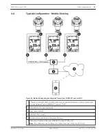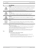
Power Cable Installation
5. Connect the power cable.
–
Prepare the cable as needed.
–
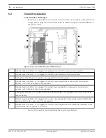
Feed the cable through an appropriate cable gland or conduit hole near where the 3-pin
terminal plug connector for the mains power cable will be installed on the PCBA (item 3).
–
Connect the cable wires to the connector according to the table below.
Pin
Description / Function
1
Line voltage
2
No connection
3
Neutral voltage
–
Check that the connections are secure.
–
Carefully press the connector to the appropriate location on the PCBA.
–
Ground the chassis.
–
Remove the brass nut and copper washer from the earth termination post (item 1
closest to item 2); set these aside.
–
Remove the ring terminal (supplied).
–
Insert the earth core from the mains cord into the ring terminal and crimp it in place.
–
Place the ring terminal onto the earth termination post.
–
Replace the copper washer. Secure with the brass nut.
Ethernet Cables Installation
6. Connect the HPoE Ethernet cable.
–
Feed an Ethernet cable from the IP camera through an appropriate cable gland or conduit
hole near the port labeled PoE on the PCBA (item 12).
–
Connect the cable to the port on the PCBA.
Note: Do not remove the protective material over the PCBA.
7. Connect network Ethernet cable(s), if applicable.
–
Feed an Ethernet cable (Cat5e/Cat6e rated to 350 MHz) from the head-end network
through an appropriate cable gland or conduit hole near the RJ45 ports labeled ETH1 and
ETH2 (item 11).
–
Connect the cable to one of the ports.
–
If connecting to another network device (such as a second VIDEOJET connect 7000 unit),
feed an Ethernet cable through an appropriate cable gland or conduit hole and connect it
to the RJ45 port labeled ETH2 (item 11).
Fiber Installation
8. Install SFP modules, if applicable.
–
Install SFP module(s) into the SFP socket(s) (item 10). Refer to the installation
instructions of the manufacturer of your chosen SFP module. Refer to the section
Optional Accessories, page 12 for recommendations.
–
Feed fiber optic cable from the external device through an appropriate cable gland or
conduit hole near the SFP socket(s).
–
Terminate the cable.
–
Connect the cable to the appropriate SFP socket(s).
5.4
5.5
5.6
24
en | Installation
VIDEOJET connect 7000
2014.10 | 1.4 | F.01U.291.524
Operation Manual
Bosch Security Systems
Содержание VIDEOJET connect 7000
Страница 1: ...VIDEOJET connect 7000 VJC 7000 90 en Operation Manual ...
Страница 2: ......
Страница 58: ......
Страница 59: ......


