


Alarm Inputs
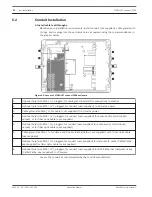
9. Connect Alarm inputs, if applicable.
–
Prepare the cable as needed.
–
Feed the cable through an appropriate cable gland or conduit hole near where the 6-pin
terminal plug connector for alarm inputs will be installed on the PCBA (item 8).
–
Make the connections for alarm inputs (for external devices such as door contacts or
sensors) to the connector according to the table below.
Pin
Description / Function
1
Alarm 2
2
Ground
3
Alarm 3
4
Alarm 4
5
Ground
6
Alarm 5
Note: You can use a zero potential closing contact or switch as the actuator. If possible, use a
bounce-free contact system as the actuator.
–
Check that the connections are secure.
–
Carefully press the connector to the appropriate location on the PCBA.
Alarm Outputs
10. Connect Alarm outputs, if applicable.
–
Prepare the cable as needed.
–
Feed the cable through an appropriate cable gland or conduit hole near where the 7-pin
terminal plug connector for alarm outputs will be installed on the PCBA (item 7).
–
Make the connections for relay outputs (for switching external units such as lamps or
alarm sirens) to the connector according to the table below.
Pin
Description / Function
1
Ground
2
Alarm Output 1
3
Ground
4
Alarm Output 2
5
Alarm Output 3
6
Ground
7
Tamper (Alarm 1)
–
Check that the connections are secure.
–
Carefully press the connector to the appropriate location on the PCBA.
Washer Pump
11. Connect the washer pump drive, if applicable.
–
Prepare the cable as needed.
5.7
5.8
5.9
VIDEOJET connect 7000
Installation | en
25
Bosch Security Systems
Operation Manual
2014.10 | 1.4 | F.01U.291.524
Содержание VIDEOJET connect 7000
Страница 1: ...VIDEOJET connect 7000 VJC 7000 90 en Operation Manual ...
Страница 2: ......
Страница 58: ......
Страница 59: ......


