


Conduit Installation
4. Install cable feed-throughs.
–
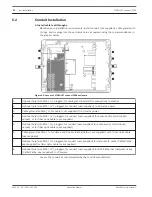
Based on your installation requirements, install conduit (not supplied), cable glands with
O-rings, and/or plugs into the enclosure holes as needed, using the recommendations in
the graphic below.
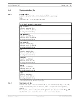
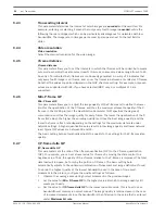
Figure 5.2: Layout of VIDEOJET connect 7000 enclosure
1
Optional hole (size M16 / ½), plugged, for cable gland intended for connections to washer
2
Optional hole (size M25 / ¾”), plugged, for conduit (user-supplied) to AC mains power
3
Cable gland, size M16 / ½, for cable (user-supplied) to AC mains power
4
Optional hole (size M25 / ¾”), plugged, for conduit (user-supplied) for audio and/or alarm inputs/
outputs, or for fiber optic cable (user-supplied)
5
Optional hole (size M16 / ½), plugged, for conduit (user-supplied) for audio and/or alarm inputs/
outputs, or for fiber optic cable (user-supplied)
6
Cable gland, size M16 / ½, for data-only IP cable (Cat5e/Cat6e, user-supplied) or for fiber optic cable
(user-supplied)
7
Optional hole (size M16 / ½), plugged, for conduit (user-supplied) for data-only IP cable (Cat5e/Cat6e,
user-supplied) or fiber optic cable (user-supplied)
8
Optional hole (size M25 / ¾”), plugged, for conduit (user-supplied) for HPoE Ethernet (network) cable
(Cat5e/Cat6e, user-supplied) to IP camera
–
Secure the conduit as recommended by the conduit manufacturer.
5.2
22
en | Installation
VIDEOJET connect 7000
2014.10 | 1.4 | F.01U.291.524
Operation Manual
Bosch Security Systems
Содержание VIDEOJET connect 7000
Страница 1: ...VIDEOJET connect 7000 VJC 7000 90 en Operation Manual ...
Страница 2: ......
Страница 58: ......
Страница 59: ......


