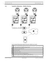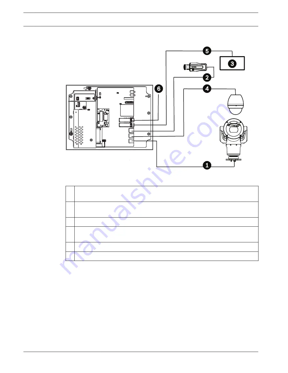
Typical Configuration - Multiple Cameras to Head-end Network
Cat5e/Cat6e = 100 m max.
1
1
Figure 3.3: Multiple cameras to VIDEOJET connect 7000
1 Ethernet (network) cable (Cat5e/Cat6e) (user-supplied) between a Bosch camera and
the port labeled PoE on VIDEOJET connect 7000
2 Data-only IP cable (Cat5e/Cat6e) between a Bosch IP camera and the port labeled ETH 2
on VIDEOJET connect 7000
3 Head-end network
4 Data-only IP cable (Cat5e/Cat6e) between a Bosch camera and the port labeled ETH 1
on VIDEOJET connect 7000
5 Fiber optic cable to the head-end network
6 Fiber optic cable to the next VIDEOJET connect 7000unit (if applicable)
3.3
16
en | Product Overview
VIDEOJET connect 7000
2014.10 | 1.4 | F.01U.291.524
Operation Manual
Bosch Security Systems
Содержание VIDEOJET connect 7000
Страница 1: ...VIDEOJET connect 7000 VJC 7000 90 en Operation Manual ...
Страница 2: ......
Страница 58: ......
Страница 59: ......


