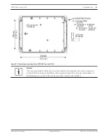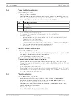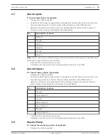
PCBA Connections
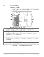
Note: Use the figure below of the layout of the Printed Circuit Board Assembly (PCBA) as
reference when completing steps 5 – 12.
Figure 5.3: Layout of VIDEOJET connect 7000 PCBA
1
Ground lug
2
Terminal block (2-pin) for connections to optional washer
3
Terminal plug connector (3-pin) for AC mains power input
4
Push button to activate/test the washer
5
Audio OUT
6
Audio IN
7
Terminal plug connector (7-pin) for alarm outputs and tamper switch
8
Terminal plug connector (6-pin) for alarm inputs
9
One (1) slot for optional CompactFlash (CF) memory card, Type I / Type II, 32 GB max (user-supplied)
10
Two (2) slots for use with SFP-based fiber optic modules (1GB only) (user-supplied)
11
Two (2) RJ45 Ethernet (female) ports (labeled ETH1, ETH2)
12
One (1) RJ45 HPoE Ethernet (female) port (labeled PoE)
Note: The protective material over the PCBA is not shown.
5.3
VIDEOJET connect 7000
Installation | en
23
Bosch Security Systems
Operation Manual
2014.10 | 1.4 | F.01U.291.524
Содержание VIDEOJET connect 7000
Страница 1: ...VIDEOJET connect 7000 VJC 7000 90 en Operation Manual ...
Страница 2: ......
Страница 58: ......
Страница 59: ......


